Showing posts with label diy. Show all posts

Saturday, 11 April 2026

My Project Workflow

Projects can take a long time to bring to fruition. This means that I often have several on the go at the same time, which in turn can cause me to miss out some important steps. So I thought I'd gather all of the tips and tricks I've learned in one place as a reference.

The idea
  • scratch an itch
  • read other makers (for example on hackaday)
  • that new-fangled youtube can be useful too
Prototype
  • use a breadboard and dupont connectors for speed
  • sketch the schematic on paper as you go
  • use an llm for advice or as a search engine to find similar projects
  • plagiarise other people's designs, you might find one which does everything you need
Schematic
  • break out KiCad or similar and copy the paper schematic
  • separate subsystems and connect with labels
  • add test points (and expansion points if that makes sense)
  • use the electrical rules checker
  • rebuild the schematic on breadboard to test it
PCB Design
  • add component footprints
  • use the design rules checker
  • print the PCB at 1:1 on paper and check footprints
  • make holes in the paper with a pin and check footprints again!
  • use a ground plane and mounting holes
  • use the silk-screen for component values, labels and version information
  • add your email address (you never know)
  • use a plugin to send your design for fabrication (for example to PCBWay)
  • save the design and its firmware in version control (for example GitHub)
Board Assembly
  • don't rush!
  • add low-profile components first
  • socket everything you might want to reuse
  • solder up each subsystem and test immediately
  • clean off flux with isopropyl alcohol and a toothbrush
Post Mortem
  • if it works, document it on a blog like this one
  • if it doesn't, fix it immediately, update the version, and document it on a blog like this one
  • don't worry about anyone caring about your successes or failures!


Thursday, 14 March 2024

TommyPROM

Some time ago, I mentioned that I had been unable to test the various ROMs in the UK101, lacking an EPROM programmer. That has now been rectified, thanks to the fine work of Tom Nisbet, creator of TommyPROM. 

In addition to an Arduino sketch, the Github linked above hosts a couple of circuit boards, and I had them made as part of my last order from Seeed Studio.

TommyPROM with a very old 2716 EPROM

Populating this PCB cost under €10, quite the bargain. This version of the programmer can read 27-series EPROMs but can't manage the voltages required to program them.

Configuring the programmer requires editing the Arduino sketch for chip series and type, and uploading the modified sketch. This wouldn't pass muster in a commercial product but is absolutely fine for this project's target market: hobbyists on a budget.

Opening a serial port to the board shows the following menu:

Main Menu

Reading that EPROM, which is nearly 40 years old, produced the following output:

Amnesia?

Unsurprisingly, given its age, it seems to have lost its memory! Luckily it is not too difficult to find copies of UK101 (and Superboard) firmware online, Mark's Lab has copies for instance.

Burning old-school 27-series EPROMs requires more advanced hardware, and the second TommyPROM board I had made can do it, TommyPROM32. I will review that iteration when I have assembled it.

What the current version of TommyPROM can do is write to 28-series EEPROMs, e.g., an AT28C16. This is pin-compatible with the 2716 so once it arrives and has been programmed, the next step in testing the UK101 can be taken: hooking the board up to a logic analyser and spying on the data bus using another fine Open Source tool: 6502Decoder.

(I have several PCBs left over from that order. If you want one at cost, PM me.)

Update (April 2024): after some further investigation, it turns out that the basic TommyPROM can only handle 28-pin chips so any data retrieved from smaller chips (as above) won't be valid. TommyPROM32 is definitely the way to go here. Stay tuned for a review of that coming soon!


Tuesday, 9 January 2024

Testing ICs


It seems like about two years ago, IC testers made quite a splash, judging by reviews of the Retro Chip Tester Pro (Adrian's Digital Basement) and the BackBit Chip Tester Pro (Noel's Retro Lab). Nice products though they are, they are a little out of my price range for this project.

TTL testing

Luckily for my wallet, there are several DIY projects out there which can be assembled from commonly-available parts in not too long. Nick Gammon (who's excellent interrupt and power-saving pages were inspiration for my Interrupted project) has a super-simple one which can be assembled on a breadboard in about an hour for the cost of 16 resistors, some dupont connectors and an Arduino Uno!

It ain't pretty but it works!

Nick credits an Instructable by one "JorBi" for inspiration for his work. That project is more elaborate, using an Arduino Nano and a display --- Nick's just uses the Arduino serial port, nothing wrong with that. JorBi's project also provided the data file containing the actual chip tests: JorBi stores this in an EPROM while Nick puts it in the on-chip flash.

Another tester of note is the Smart-IC-Tester: an Arduino shield with TFT display. This stores the test database on an SD card, in a format very similar to JorBi's, just adding a one-line description to each part.

So? Well out of 34 74-series TTL chips on the UK101, Nick's tester flagged 7 as bad, 15 as good, 4 were unknown and 8 not tested, due to having wires soldered to them. Not bad for a day's work!

The bad chips were as follows:

  • Two 74125s
  • Three 74123s (all from the same batch)
  • One 7403
  • One 7404 (in bad shape, one pin broke off in the socket)
Note, it could be that the 74123 and 74125 tests are incorrect. I have none which tested good.

Update: After playing with the IC-Tester for a while longer, I managed to add tests for the hitherto-unknown chips. The latest score is 9 bad, 22 good and 3 not tested. My fork of Nick's repo is here.

Update 2: I built this circuit on a piece of vero board and piggy-backed it onto my home-brew Uno!
An improvement anyway!

Memory testing

In addition to the discrete TTL chips, the UK101 also had 32 2114 static RAM for main memory and another 4 for the display. Nick's tester is unable to test this IC. Luckily somone named "skjerk" has written a sketch for the Arduino Uno which does exactly this.

The 2114 has a pretty bad rep when it comes to living into old age so I didn't hold out much hope for my set. Rather incredibly however they all came up good!

Untested so far

Chips which I haven't been able to test yet:
  • The 6502 and 6851
  • The Basic ROMs and Character Generator ROM
  • The monitor EPROM

Given an EPROM programmer, it should be possible to read the ROMs and compute their checksums. Stay tuned for that!

Of course the two commercial testers mentioned above can test all of these chips, out-of-the-box. But where's the fun in that?

Thursday, 27 August 2020

Soldering surface-mount components


ncp1402 boost converter


The image shows a breakout board for an NCP1402-based boost converter which steps-up 1.5v to 5v; these circuits are widely-used to power 5v (or nowadays 3.3v) from a single coin cell. (The board is my design, in KiCad, based on the manufacturer's recommended application.)

Of more interest here is the regulator component itself. This is the small 5-pin chip midway up the right-hand side of the board. It is a surface-mount SOT23-5 part, approximately 3mm by 1.5mm, far smaller than a grain of rice. Building this breakout board was more an exercise in seeing if it was possible to hand-solder these parts than anything else, since they are widely available for cheap on t'Internet.

So how did I do it? The first step was choosing a hand-soldered footprint for the part in KiCad. Then, once the boards had arrived, this part obviously had to be soldered on first:

  • Apply solder to the pad under one of the further-apart pins (on the left in the picture)
  • Place the chip over this pad with a tweezers and hold it in place
  • Melt the solder on the pad until it flows over the pin
  • Solder the other pin on the left-hand side
  • Solder the three pins on the right-hand side together. 
  • With a desoldering pump (braid should work too), remove the excess solder from these three pins, so they are no longer shorted together.
Tweezers and magnifying glass (or low-power microscope) are essential, unless you are some sort of assembly robot. Fine-gauge solder and a fine-tipped soldering are helpful too.

Note that the circuit itself helped me "get away" with the final two steps of the procedure above: of the three pins on that side of the regulator, one is NC and the other two are connected to Vout. However checking with a continuity tester indicated that they were no longer shorted together, so the pump had worked as expected.

So the experiment being successful, the next step is to build more surface-mount parts into my designs. 10k resistors and 100n capacitors crop up very often so they would be obvious targets for replacement. Stay tuned!

Wednesday, 22 July 2020

Simple Variable Voltage Bench PSU

Back in the days of the desktop PC, a common DIY project was to re-use its ATX power supply as the basis of a Bench PSU. Sadly those days are slipping into the past as more and more of us move to laptops. All is not lost however, as most laptop transformers also deliver a reasonable output voltage which can easily be down-regulated and supplied to nascent bench projects.


The circuit schematic could hardly be simpler --- I am fairly embarrassed that the best I could do to obtain it for insertion here was "Print Screen" in KiCad. All of the action is provided by an LM317 linear regulator which costs peanuts these days. The output voltage is given by:

Vout = Vref * (1 + RV1 / R1), Vref = 1.25v

Note that this is independent of the input voltage, although obviously it can't be greater. Also we want to choose R1 so that the output is at sensible values for differing positions of the (linear) potentiometer RV1. Given a transformer rated at 19v, we choose R1 = 680R, giving values of Vout:

RV1    Vout 
0      1.25
2k5    5.8
5k     10.4
7k5    15
10k    19.6

Obviously the last value is a little too high, however this value of R1 gives the greatest precision for the transformer at hand.

The design is completed with a cheap LED voltmeter as shown below.


Simple extensions to this design would be to use a combined Voltmeter/Ammeter display (also costing peanuts); adding a current-limiting circuit, or a switched constant-current source, also supported by the LM317. Next time!

Friday, 19 July 2019

KiCad Kata

Pretty (but dumb) LED Matrix
The picture shows the result of another workout with KiCad as executed by Seeed Studio and finished by me. This looks rather prettier than the original and was considerably easier to solder, not to mention more LEDs!

However a few defects are obvious too:

  • the LED spacing is wider than on stripboard, which can make patterns harder to discern
  • the interface split between anodes and cathodes is the same as the original, for no good reason
  • it now uses 16 gpios!
The first and second of these are my fault but the last could have been mitigated by adding an LED driver, such as the MAX7221 to the design:
MAX7221 DIP package
This particular chip requires only a couple of capacitors and a single resistor to function (see the circuit here). Also it is cheap, less than €1 from China and has a mature Arduino library. It could comfortably have fit in the space occupied by the resistors on the left of the picture. On the downside, it requires a 5v supply. (The Arduino playground has a lot of information about it.)

So, it was instructive to lay out an LED matrix and write a library for it, and I'd encourage you to try it for yourself. (However I also won't blame you for simply buying one on eBay, they seem to be cheaper than the cost of parts somehow!)

Wednesday, 22 May 2019

Soldering Kata

7x7 LED Matrix
When I were a lad, LEDs were a big deal, literally: £1 each. Now someone in China manages to make a living selling them for £1 for 100. With inspiration provided by an Instructable, a rainy afternoon and the need for some soldering practice I set to work.

The Instructable's, err, instructions were clear enough:

  • take a piece of protoboard (the sort with pads instead of strips)
  • solder each row of LEDs anode (longer) first to hold them in place
  • cut the cathodes to size and bend them through 90 to connect each row's together
  • test each row after soldering!
  • I then cut a piece of stripboard ("veroboard") into single strips and connected each column's anodes together in a sort of DIY dual-layer PCB arrangement, see below.

Rear view: anodes connected in columns

The last step was the only point where I deviated from the instructions. (I first attempted to fit a single piece of veroboard over all of the anodes but found this impossible: there was too much variation in their positions. Perhaps aligning each row of LEDs as it is soldered using veroboard might work?)

Next: mount vertically on breadboard, add a handful of resistors (470R) and connect to an Arduino!

I wrote an Arduino library for it, available on Github. It contains a couple of examples, the simplest can be seen running below. (The moving light makes keeping the camera focussed impossible, sorry.)


The disadvantages of this bit-banging approach to driving an LED matrix are fairly well-known:
  • it uses an excessive number of GPIOs (14 here)
  • the GPIOs themselves can't supply very much current, so the more LEDs lit, the dimmer they are
  • PWM-style dimming is not practical
  • timing is tricky: since it relies on persistence of vision to work, each refresh cycle must take no more than 40ms
For all of these reasons, using a dedicated driver chip is recommended. More when my MAX7221 (another £1) arrives on the ship from China in a couple of weeks!

Friday, 26 August 2016

A Tinier Tiny

Now even tinier!
The photo shows an upgrade to last year's tiny ATtiny development board: now even smaller and with fewer components but with better breadboard performance!

The schematic and board layout (for Eagle) along with gerbers can be found here. The pcb (from Seeed, 1€) was cut down to size with a Dremel.

Saturday, 29 August 2015

Simple Breadboard Power Supply

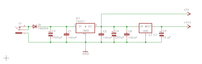
It's very satisfying to build something for which you've all the parts to hand, there's no waiting around, just immediate gratification. This little build is such a thing. It's a dual-voltage (5v and 3.3v) power supply which plugs into a breadboard and is handy for projects which aren't powered from a USB tether (e.g., wireless microcontroller prototypes or projects which don't use a microcontroller at all, hard as that might be to believe).


It's loosely based on the circuit below, although I used different values for the capacitors, having first done a bit of research to discover that the 100nF ones are used to filter high-frequency noise. If I have problems with that in the future I'll add them.

Sunday, 10 November 2013

ATtiny Development Board... now with added Bootloader!

Not long after writing about how ATtinys have no bootloader support, I came across Adafruit's Trinket, an obviously-bootloaded ATtiny85! However as this board's USB bootloader consumes over 2.5kB of flash, it could not coexist with wireless networking in the form of the RF24 library I'm interested in (which leaves only 2.5kB free after inclusion).

Nevertheless, googling "attiny bootloader" turns up several interesting links, notably TinySafeBoot. This is both tiny (550 bytes) and safe (providing password support). Its size means there's still almost 2kB left free in my desired configuration which I expect should be enough for some interesting wireless sensing applications --- stay tuned for more on that.

TSB, which is GPL-licensed, comes with a generic AVR bootloader blob which it tunes for your target hardware, rather than requiring messing with makefiles and building-from-source. In the case of our ATtiny development board, the desired target is an ATtiny84 with pins PB1 and PB0 connected to software-serial Rx/Tx:
% ./tsb tn84 b1b0  # generates tsb_tn84_b1b0_20131023.hex
The resulting bootloader can now be uploaded to the development board using an external programmer. Thereafter TSB talks to the bootloader to upload programs:
% ./tsb /dev/ttyUSB0 FW Blink.cpp.hex
(The bootloader auto-detects the bit-rate which the uploader is using; here I'm just taking the default of 9600B.)

The obvious next step is to integrate TSB into the Arduino IDE, building on the Jeelabs' work to obtain an environment indistinguishable from a normal ATmega-based Arduino; it would simply replace that part of platform.txt, specifying tsb, with appropriate flags, as the uploader.

Unfortunately, I think due to the way tsb handles its input stream, it doesn't take kindly to being called from a script; it's written in freebasic, maybe it's a feature of that platform. So, with the help of strace, I wrote a one-shot firmware uploader in C (gist here) callable from the Arduino IDE.

Now I can upload sketches from the Arduino IDE to my ATtiny development board without any additional hardware! The 'burn bootloader' functionality also works (with the aid of an external programmer) to burn fuses and install the custom firmware file generated above. My fork of Jeelabs' repository is available here, just clone it into your sketchbook/hardware folder.

The only hardware modification I made to my development board was the addition of a series 100nF ceramic capacitor between reset and DTR, to reset the ATtiny when the IDE wants to upload a sketch via FTDI.

Update

A diagram showing the pin names of the ATtiny84 in the Arduino IDE:
Here's a circuit diagram:
The schottky diode acts as a block to allow the board to be powered from an external battery. In this mode, the LED is disabled and no reverse current flows through the regulator. A schottky diode was used because of its low forward voltage drop (0.4v); an ordinary diode would drop the 3.3v supply to 2.6v. (Maybe that's why 3.6v regulators exist!)

Sunday, 3 November 2013

Homebrew msp430 Development Board

While not exclusively devoted to AVR microcontrollers, this blog has concentrated on them for one simple reason: they are very easy to get started with. Whether for beginner (Arduino) or professional (GNU make and gcc), the software ecosystem is very mature. Furthermore, a proliferation of cheap Arduinos (and clones) means that even lack of hardware experience is no barrier to entry.

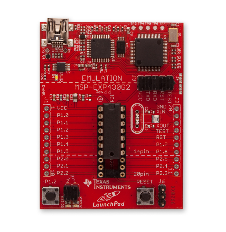
Texas Instruments has been relatively late to the party with their launchpad line of msp430-based microcontrollers and, until quite recently, a steep learning curve awaited the newcomer. That has all changed with the creation of an Arduino-compatible core for the msp430 and a fork of the Arduino software, Energia, which provides an experience almost indistinguishable from Arduino itself.
msp430 'launchpad' experimenter board

One further thing missing, until now, was ease of prototyping with the microcontrollers themselves outside of the launchpad development kits. The latter actually contain two microcontrollers, one to act as a usb programmer and the other to run user-programs. (While the first actually provides more features than that, that's all a beginner sees.) Thus a hobbyist wanting to use an msp430 for a real-world application had two choices: use the launchpad experimented board itself 'in the field', or program the microcontroller in the experimenter board and then move the newly programmed chip to its permanent home by hand. Easy field upgrades of firmware would require a more complex solution.

Such a solution has been in the works by members of the 43oh community for about a year now. This is a combined USB-stack (cf., v-usb) and bootloader which allows uploading of user programs via a simple USB cable. Only three resistors are required to support USB.

My hardware instantiation of this work (done entirely by others at 43oh and downloadable here) looks like this:
boot430 development board (with g2553)
The bootloader itself is bootstrapped using a development  board: I programmed all of my msp430s at one sitting! Once bootstrapped, user programs can be updated with a simple USB cable and a program called boot430.
Stripboard Layout

The final piece of the puzzle was programming one of these from Energia. Conventionally Energia uses an external program, mspdebug which unfortunately does not speak the same protocol as the USB bootloader. While it is unfortunately not currently possible to configure Energia to use a different uploader, this is a problem which the Arduino team has already encountered and solved in its still-beta version-1.5.

Thus, my somewhat-heretical solution to this problem (at Github): port the Energia launchpad cores back to Arduino, using the same software infrastructure as for the ATtiny development board described earlier. This seems to work quite well, although Arduino has still-unresolved issues in the area of libraries, which leads to confusion about which libraries are actually available on the current platform.

Wednesday, 4 September 2013

ATtiny84 Development Board

JNµ-alike
 This little board was inspired by a series of articles at JeeLabs describing how to program a JNµ from Arduino-1.5. (I tweaked a couple of values in its boards.txt but otherwise it's as described there.)

Background: since the ATtiny has no bootloader support, it can't be programmed with an FTDI cable but requires an ISP (e.g., an Arduino running the ArduinoISP example) to upload sketches to it over SPI, via avrdude (as seen below). The latest version of the Arduino IDE now supports this from within the IDE itself.
Programming it.
However I chose to add an FTDI connector because the authors of the arduino-tiny core had cunningly added a transmit-only serial emulation (on pin PB0 on the ATtiny84). (While a SoftwareSerial library which can also receive data exists, it's not yet supported on IDE 1.5.2. However I added future support for it anyway by wiring the receive line to PB1.)

Board layout
But wait, there's more! This fine article points out an alternative to ArduinoISP, which can also act as a serial relay: TinyISP. It provides two ways of doing this: by relaying SoftwareSerial and a (more robust) alternative called Knock-Bang. Each of these methods uses the SPI lines so no extra connector is required. This allows programming an ATtiny in almost the same way as an Arduino --- except you need an Arduino to act as a serial port for it!

Saturday, 8 June 2013

SqueezePlug LCD

Radio 4, where else?
The picture shows an lcd2usb clone attached to a SqueezePlug server running on a Raspberry Pi. It is housed in a perspex box, retrieved from a workplace bin, in which an Apple Magic Mouse was shipped. (Perspex boxes from Apple make great project housings!) The media server communicates with it via lcdproc and a homebrew perl script, made significantly simpler by the fact that both lcdproc and the Logitech Media Server provide command-line interfaces. The two switches allow playback to be paused and stopped, respectively.
Samsung Camera awesomeness!

While its firmware was used unchanged from lcd2usb, the hardware was simplified by removing the programmable contrast control, support for multiple display types and for in-system programming. Another change was necessitated by the fact that the display used (a JHD204A), while claiming to be HD44780-compatible, has its contrast and Vcc pins (2 and 3) swapped.

The circuit was assembled in typical 'backpack' style on a piece of stripboard. A nice feature of this display is that it provides connector pins at the top and bottom, allowing functions to be connected to whichever edge is most convenient. The layout was performed manually with pencil and grid-paper as shown below.

Friday, 29 March 2013

Prototyping Shield

The picture shows a nifty little 5v TFT-display and SD-card combo purchased on eBay for about €10. It is almost identical to an Adafruit product costing twice as much and since it uses the same chip (the ST7735R, should you care) it's compatible with Ladyada's library. (In fact, the Adafruit tutorial is also useful: the sole difference is that the cheapie's backlight pin should be connected to ground, rather than +5v.)
However the star of this show is the little rapid-prototyping shield shown above. It's primary purpose is to be a sort of breadboard substitute for those components which are unbreadboardable, e.g., larger TFT displays with two rows of pins, such as this one:
One way to play around with one of these guys is to solder two rows of male headers at either the left or right sides and connect it to a breadboard (or Arduino) via jumpers. However this ties up your breadboard  (or Arduino) for the duration of the experiment, which for the committed hobbyist, can be indefinite. With one of these handy shields, a slightly more permanent home can be made for your device for much less than the cost of a breadboard!

Sunday, 10 February 2013

Heroic Failures: Voice of TicBot

A project such as Magic Mouth (spotted at Dangerous Prototypes) is a fine example of the surprising power of the ATMega chip. With the addition of a simple audio amplifier and the impressive Webbotlib, your humble 8-bit microcontroller can turn English text into speech!

My first attempt at a project with a similar setup simply read text from the serial port and converted it into speech. (You can find the amplifier circuit schematic and Webbotlib code at Github here, it differs from Magic Mouth mainly by not depending on an external Arduino to supply the text to be spoken.) Here is a picture of it in all its homebrew glory; the amplifier is the little board piggybacking the Arduino clone, the 8-pin chip in the middle is an LM386.


Around the same time, I came across an article about a piece of software which tweeted tics: TicBot. While more Eliza-with-Tourettes than major AI breakthrough, it can be very funny:
Under the influence of Xmas cheer, an idea was born... Voice of TicBot! It would be a humble Arduino connected to Twitter by Ethernet, speaking TicBot's words of wisdom in a robot voice! How hard could that be?

The first obstacle was Twitter's use of OAuth; while this solves the problem of third-party web-application authentication, it is a pain for a device without a traditional UI. Thankfully the good people at supertweet.net have solved this problem, providing an OAuth proxy for Twitter to which devices authenticate themselves using good ol' Basic Auth.

It was then quite straightforward to write a little sketch which polled api.supertweet.net every 10 minutes for TicBot's timeline (using JeeLabs' handy Ethernet driver) and grubbed through the response for the id and text fields; no space for a fancy JSON parser here!

The next problem was how to combine the two applications? One an Arduino sketch (in C++) and the other a Webbotlib application (in C). Neither the option of porting the Ethernet driver to Webbotlib nor that of porting the relevant parts of Webbotlib to Arduino was particularly appealing. Moreover the combined size of the two applications exceeded the flash memory limit of the ATMega-328!

Fortunately a solution turned up in the shape of an Arduino port of Webbotlib's text-to-speech module, TTS. (This was a lucky piece of googling --- my Romanian is non-existent.) It required some work because my amplifier expected its PWM input to come from pin 3 whereas the TTS module emitted it on pin 10, which was needed for the Ethernet SPI. Adding the required functionality for PWM on pin 3 was achieved with the help of a nice online tutorial. An Arduino library updated for version 1.0 and with this functionality and some more examples (including the sketch for VoTB) can be found here.

With these problems solved, Voice of TicBot was finally operational! Unfortunately it was also a failure: the gnomic nature of TicBot's utterances combined with the low quality of the speech rendition made it necessary to visually consult twitter.com whenever output was heard! Here's an example of its output.

(All of this reminds me of a (possibly apocryphal) story about Stephen Hawking's first speech synthesizer: his students were pressed into service as translators, due, one assumes, to their familiarity both with the subject matter and the machine's vocal stylings.)

Thursday, 21 June 2012

Transistortester

One of the most enjoyable distractions of the past year has undoubtedly been MIT's online course in Circuits and Electronics. This sparked a renewed interest in discrete electronics which naturally led to the idea of measuring various parts' characteristics using AVRs. (The link with Arduino probably arose from a tutorial showing how to measure capacitance.)

Needless to say, once the idea had germinated it was only a matter of time before I spotted that someone else had done it, and much more thoroughly than I had ever planned to. An initial siting on Dangerous Prototypes led to the original German site where one Markus Frejek had done a magnificent job identifying and measuring characteristics of 15 different kinds of Semiconductor device (plus Resistors and Capacitors) using an AVR. His original design is downloadable here --- this package contains his circuit diagram with a neat transistor latch to turn off the voltage regulator when powering-down the AVR. (I didn't go with this in the end, preferring to use a momentary push-button to power it on.)

I built this circuit over the course of a day and I had translated the strings into English when I discovered that Markus's original announcement in early 2009 had led to a huge thread on mikrocontroller.net (which continues today!). His code had been taken up and extensively modified by Karl-Heinz Kübbeler. I went with the latest version (096k) which still works with the original circuit diagram.

The new software which is quite well packaged, is certainly the biggest AVR program I have seen. I edited the Makefile for the following settings:
#CFLAGS += -DNO_AREF_CAP
#CFLAGS += -DPULLUP_DISABLE
PROGRAMMER=avrisp
PORT=/dev/ttyUSB0 -b 19200
The file Transistortester.h should also be edited for the exact values of the resistors connected to the analog inputs, R_L_VAL and R_H_VAL --- test them with a multimeter before soldering them up. (It is probably worthwhile to use 1% tolerance parts.)  Then make && make upload && make fuses will program the microcontroller correctly.

A poor photo of my completed build on stripboard is shown below measuring an IN4148 diode. About the only change I'd make to this great project would be to introduce a software mapping layer for the connections between the AVR and the LCD data pins. (The default connections require a lot of cut-tracks and fiddly crossing-wires for the backpack arrangement I went with.)

It fits perfectly in an old perspex iPod nano case I found lying around!

Wednesday, 14 December 2011

Homebrew ISP Shield

Mocking up an ISP on a breadboard as described below is handy as a once-off but gets old very quickly. The pictures show a little "shield" for the homebrew Arduino, which costs about a euro for parts and a couple of hours of time.

Although this shield takes a little longer to construct than it does to wire up the breadboard, it also boasts status LEDs, for Heartbeat, Error and Programming, which ArduinoISP can drive but which were always too much trouble to wire up. (The Heartbeat LED is particularly pretty.)

Soldering it together doesn't take too much effort. The main thing to remember is to solder the headers first on a flat surface so that they are quite vertical and protrude the same distance below the board. (This is actually the trickiest part of the job.)

Since they're so cheap, there's no point not to make separate shields for the 8-pin and 14-pin Tiny AVRs. We'll do these as needed.

Thursday, 19 May 2011

It's the little things


One of the first lessons learned by anyone attempting to cook even a moderately complicated meal is do as much preparation as possible. The fewer steps which remain at runtime (as it were) the fewer the opportunities to poison guests.

As with cookery, so with hardware. Frequently-used subsystems, built and tested independently, are an invaluable aid to rapid prototyping. The picture above shows three:
  1. A power cable to carry +5v from the development board to the breadboard,
  2. A breakout board for a magnetic sensor, implementing the manufacturer's suggested circuit,
  3. An LED with 470R resistor in series (why don't manufacturers just sell these?)

Thursday, 5 May 2011

Homebrew Arduino development board

Inspired by Romilly's veroduino but requiring some hand-holding to get me started, I happened upon Oomlout's Component Bundle for Arduino Compatible --- I already had some breadboard lying around. While I was there I picked up a USB-Serial cable (which you need in order to actually program the thing).

Having assembled the kit by following the instructions for the BBAC (hint: you can use plain wire instead of 0-ohm resistors!) and tested that it was working (mostly: the cable is too heavy for the serial port header on the breadboard, it kept pulling it loose, making it next to impossible to download sketches), I decided that the thing would need a permanent home: stripboard (or veroboard as it used to be called).

Here are the bits required for a minimal development board:
  • 6-way male header
  • 2x10k
  • pushbutton (reset)
  • 2x16-way female header (14-way would do but that's all bitsbox had)
  • 16MHz crystal
  • 100nF ceramic
  • 2x22pF ceramic
  • 28-pin DIL socket
  • ATMega328 flashed with Arduino bootloader
  • Stripboard 26 lines x 15 holes
I left off the 5v DC converter circuit because the board gets its power from the host PC, via the serial cable. At your option you may wish to add a power LED, or an additional LED on pin 13, for the 'blink' demo. (The BBAC shows how to wire each of these.)

Once you have this wired up, your breadboard is freed-up for actual experimentation!

The board assembled: