Showing posts with label xbee. Show all posts

Thursday, 19 February 2015

TinySensor Server

Well after almost a year I decided it was time to update this project with improvements to both its hardware and software.

On the hardware side, the server is still the original Raspberry Pi model B, but I've mounted the nRF24L01+ radio on a neat little Slice of Pi board. (These boards also have traces for mounting XBees with their unusual pin spacing. And they're cheap!)

The Slice of Pi board (left) with radio and status LEDs
While I had the soldering iron out, I added a couple of status LEDs (see picture). The green one indicates recent activity on the radio, while the red one indicates a timeout but also flashes every time a packet is received. Both of them are driven by a single GPIO line on the Pi. (This was motivated by the radio cutting out on the Pi, probably due to the original Heath-Robinson jumper cable arrangement, and since its transplant it's behaved perfectly.)

On the software side, there are now quite a few little daemons, each doing one thing well:
  • A wireless hub, running RF24-rpi, sends packets received on a TCP socket,
  • A wired hub, running remotely, polls a legacy 1-wire sensor network and sends its readings on another TCP socket,
  • A multiplexor, connected to the two data sources above, sends their streams to its connected clients, described next,
  • A MySQL client writes readings to a database,
  • A status client manages the LEDs described above,
  • An RRD client maintains a round-robin database,
  • An lcdproc client updates a wireless LCD display.
All of these are, as usual, on GitHub.

Future software components planned for this system include a simple weather service to inject local weather data into the stream, and a client for one of the various IoT services now becoming widespread. (Here is a fairly recent overview of some of these.)

Friday, 13 April 2012

Mock Pertelian


The last post concluded with a shopping list of requirements for a workable wireless display. The picture above shows a prototype of such a thing. In particular:
  • It doesn't try to be too clever: it uses an XBee as a wireless serial port and lets an ATMega do the heavy lifting, driving the display in 8-bit mode.
  • It is compatible with an existing lcdproc driver, pertelian, hence the name.
  • It bites the bullet and uses an external supply rather than batteries.
The backlight is turned on by touching a metal bolt on the top of the case. This bolt is wired to one of the ATMega's analog inputs via a solder tag. The case itself is a cheap perspex box costing about £1 from eBay.

The circuit diagram and Arduino sketch are shown below.


Update: after running for a week or so at 9600 baud, the 20x4 display was messed up. Although I never got to the bottom of it, the fault lay in the transmitting XBee: unless it was power-cycled, the problem persisted through reboots of the display and the box running LCDd. A successful workaround was to run all parts of the system at 57600 baud, i.e., both serial ports and both XBees.

Friday, 17 February 2012

Heroic Failures #1

This is the first in a (hopefully short) series of posts describing things which seemed possible beforehand but which turned out unsatisfactorily. It is inspired by a quote from Fred Brooks (via Nat) "Good judgement is the result of experience ... Experience is the result of bad judgement."

The initial motivation was dissatisfaction with the fact that all current (to my knowledge) lcdproc displays must be tethered to their host by either USB or Serial and that they might be much more useful if they could be positioned where they were needed.  When this was coupled to the observation that XBees are pretty smart and have lots of I/O, it seemed that driving a 4-line LCD display directly from an XBee using a couple of AA batteries might be a runner. The circuit is shown below and shows the display being driven in 4-bit mode with a couple of extra lines for EN and RS (I could only find a Series-1 Eagle part and used a Series-2 XBee so some of the pin names are a bit off).


One hacked lcdproc driver and some low-level XBee and LCD C-programming later, it worked... but only just!
  • The display wouldn't work properly with 3.3v: it required 5v and hence another regulator for the XBee, e.g., an Explorer Regulated breakout board,
  • It also wouldn't work (for very long anyway) on batteries: when its backlight was on, the display drew 150mA,
  • Maintaining an out-of-tree driver (for lcdproc) is painful,
  • It is extremely slow (about 1 char/sec). This is because each bit is framed in an XBee packet (thus requiring ~100 bytes to get one character to the display).

Friday, 11 November 2011

Remote Sensing with XBees, Software

In order to send AT commands to a remote device, a Coordinator must be in API mode while an End Device can be in either API or AT mode. Putting the Coordinator into API mode requires updating its firmware using a USB-Serial converter and a program called X-CTU (downloadable from digi.com). X-CTU requires Windows to run but it works fine in a VirtualBox, once you plumb through the serial device.

When X-CTU can see your device, read the modem parameters and firmware, change the function set to Coordinator API, and write the firmware back to the device. (If the firmware version on the chip does not support the Coordinator API function set, you will have to pick one which does. Unfortunately, as far as I can tell, the only way to do this is by trial and error: it seems that X-CTU will happily write firmware which doesn't run properly on the XBee. Luckily, Digi's technical support is excellent.)

To send an AT command to a remote device, it must be wrapped in a remote-AT command-frame addressed to the end device and transmitted to it via the coordinator. This is tricky! Eventually I found some Perl bindings which did the trick but before that I had some fun crafting the packets by hand, aided by a handy packet-checker. (That site also hosts a useful FAQ.)

The little script below shows how to set up the end device to read its sensors periodically and transmit them to the coordinator. This is attached to the machine on which this script runs, on a USB-Serial port. Received frames are written to the console.

Friday, 30 September 2011

Remote Sensing with XBees, Hardware

The schematic below shows a battery-powered wireless remote temperature and humidity sensor. The wireless part is provided by an XBee Pro Series 2, the humidity sensor is an HIH-4030 and the temperature sensor is an LM335a.


The XBee is configured as an 'end-device' and periodically transmits three analog samples to its 'coordinator': humidity on AD0, temperature on AD1 and supply voltage on AD2.

The most important design decision was to run the XBee standalone, without the aid of a microcontroller, which had several consequences for the resulting circuit:
  1. It constrained the choice of humidity sensor to the relatively-expensive Honeywell part, which outputs a voltage proportional to temperature. (Cheaper parts, such as this one, output digital data requiring a microcontroller to present it to the XBee.) 
  2. The Honeywell part demands a 5v supply, and the XBee no more than 3.3v, entailing the further purchase of an Explorer Regulated to step-down the supply voltage for the XBee. (This is not shown in the diagram.)
  3. The analog inputs on the XBee can only read up to 1.2v, so each sensor's output must be passed through a resistive divider to scale it down.
  4. To conserve power, the XBee spends most of its time asleep, waking only to read the sensors. Its ON/SLEEP pin is asserted when it wakes but, of course, doesn't supply the correct voltage for the sensors, so a transistor is needed to switch the 5v supply.
Had the decision to use a microcontroller been taken instead (using an ATtiny85v, say) the entire circuit could have run from 3v, considerably reducing cost and hardware-complexity.

(The diagram was made with Eagle for which Sparkfun provides a library of circuit elements for most of the parts it supplies.)

The software side of this project will be described in a subsequent posting.

Sunday, 5 June 2011

XBees are Great - Part 1

I wanted to create some remote sensors for a project recently. I needed a Passive Infra-Red (PIR) sensor, an RFID card reader/writer and a gesture sensor based on photo resistors. I wanted them to be wirelessly connected so that I could place the boxes wherever I wanted without having to worry about wiring issues.
I chose to use XBee wireless modules for the communications. They use a protocol called ZigBee designed for low power applications with limited distance communications, rather like Bluetooth but better designed. I had heard favourable reports about XBees and decided to try them out.

The selling features for me were that they:
  • Form themselves into a mesh network without any commands from me.
  • Can send serial data from one radio to another
  • Have up to ten digital I/O ports
  • Have up to four analogue input ports
  • Can periodically send input readings to a controller radio.
  • Input pins can be interrogated remotely
  • Output pins can be set remotely

The radios run off 3.3V but can tolerate 5V on the I/O pins. The analogue input ports measure 0v to 3.3V and produce a number in the range 0-255.

These features mean that the radios can be used stand-alone for many applications (switched, LEDs, voltage measurement) or with an Arduino for more complex applications.

I bought some from eBay. I got Series 2 radios as they have more features than Series 1 and I would recommend getting Series 2 if you buy some; Series 1 and Series 2 radios are not compatible. Obviously you need a minimum of two radios! As you can see in the picture above, XBee radios are small printed circuit boards with a wire or chip antenna on top and two rows of connectors on the bottom.

I also bought at the same time some XBee shields for my Arduinos. These shields look like this:


This was a mistake. I certainly did not need more than the number of Arduinos that I had. Also I discovered that none of the I/O pins on the XBee, once it is plugged in to the shield, are connected to the Arduino, wires have to be soldered in to achieve this. Another thing I did not like about the shield was that some of the Arduino's pins are hidden and become unavailable.

Mistake two was not having a way of connecting a USB cable to an XBee for programming it as a controller or a router. You need one controller in a network, the others, the routers, obtain addresses from the controller.

I found some Sparkfun boards that fitted the bill and bought some of those. The one below connects a USB cable with a standard mini-USB connector to the XBee. This board can be used for reflashing the firmware to con figure the radio or it can be used to connect a desktop or laptop to the radio system to give access to the other radios. The only way to reflash the firmware for reconfiguration or upgrading the firmware is to use a special configuration program (XCTU) on a Windows computer. The site says that it will not work on 64 bit systems but it does, I have had no problem using Windows 7 on a 64 bit system.


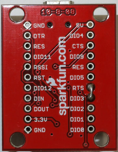
The other boards I bought for the XBees were simply breakout boards allowing me to plug the XBee into a breadboard if I wanted to. These boards also have a 5V to 3.3V converter allowing 5V to be used to power everything if desired.


These boards have to have header strips added to them to be able to plug them into a breadboard. I used one board with a four pin header on the end of the board for serial communications and power and ground.

(This article will be continued with some simple use cases)