 |
| An ATtiny84 and nrf24l01+ transceiver |
Luckily for us, someone called Maniacbug has produced an excellent pair of libraries (RF24 and RF24Network) which simplify use of these devices considerably, and in a manner consistent with the Arduino way. The latter library makes building meshed wireless networks very easy indeed. (If you're thinking XBee at a twentieth-the-cost, you're way ahead of me.) An RF24Network article describes the design and implementation of an impressively low-cost, whole-building, wireless sensor network scalable to thousands of sensors.
While reading about this sensor network, a question arose: why was it restricted to ATmegas? Surely an ATtiny would be equally up to the job? It turns out that I wasn't the first to think about this. One source of problems was the ambiguous nature of the SPI interface on ATtiny chips.
 |
| ATtiny-x5 |
Although these chips have pins named after SPI functions (SCK, MISO, MOSI) they are primarily for programming the chip over SPI, not for use in the SPI master role, to control other devices. However USI (for Universal Serial Interface), which can be used to implement SPI, is provided. In principle, therefore, it should be possible to talk to an nrf24l01 radio from an ATtiny, and it turns out by forking the Mirf library, it has been done.
My cross-platform SPI library is here, (credit is due to Nick Gammon, SPI85 and JeeLib's RF12 driver). It supports ATtiny-x4 and -x5 as well as ATmegas.
 |
| ATtiny-x4 |
Armed with this library, and the ATtiny development environment described yesterday, it was a simple matter to compile the helloworld_tx example from RF24Network. And, while it compiled fine, it failed to link because the resulting binary was too large for the ATtiny84's 8kB code space. An inspection of the library code revealed extensive use of printf_P, which eats up a lot of flash space on an ATtiny. A quick hack with the C preprocessor and the code size was down to 5700 bytes, leaving a couple of kB for user sketches.
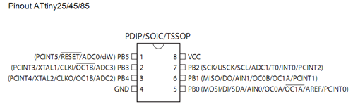
When connecting a radio, DO connects to MOSI, DI to MISO and USCK to SCK. CE and CSN can be set to anything reasonable (check cores/tiny/pins_arduino.c for the Arduino pin mappings).
Here are my forked RF24 and RF24Network libraries.
Hi, whanted to thank you for that post! Would you mind posting the pin connections to ATtiny85/84? I've tryed guessing from the code but something is not working for me. Same code works on Mega328.
ReplyDeleteThanks again!
Good idea. I've added some explanation of the SPI mappings and connecting to a radio. Hope it helps!
DeleteThank you!
ReplyDeleteHello. Before anything, thank you for the sharing of your work.
ReplyDeleteI would like to know one thing, since you went to Jee Labs for some inspiration and base work, did you consider having encryption in your fork of the RF24, with xxtea like Jee Labs has on is, for the RF he uses?
Thank you.
I hadn't noticed that feature, it's interesting! It might even be possible to add it in the ATtiny's remaining space. Not sure if it would leave much room for the actual sketch though!
DeleteTo be clear though: all I did with RF24 was blindly reduce its footprint for ATtiny. I didn't think about changing it in any other way. It would probably be better to ask Maniacbug to add it to his upstream codebase? (More room on the ATmega anyway.)
Hi Steve..
ReplyDeleteI'm the blogger for http://arduino-for-beginners.blogspot.com/ and I'm glad to find your blog...
I had made these attiny84 PCB and was trying to get the RF24 to compile on the attiny84... luckily I found your SPI forks for attiny from a mentioned on the Arduino forum...
I'm able to upload the codes to the attiny84 but my Arduino as a hub codes was not receiving anything from the attiny84/nRF ...
Without all those print_details statements, how do I know if the radio is working ?? How do you do the debugging ?
My Tiny nRF PCBs :
http://farm4.staticflickr.com/3758/12700701585_491d93ff84.jpg
Hi Stanley,
DeleteAs far as I can remember now (it's been about a year since the original investigation) I had a pretty hard time getting it all working initially.
I ended up with two ATmegas running Maniacbug's code (with prints) trying to talk to each other (and failing) until I put decoupling capacitors across the radios' power pins. Once this was working, I kept one ATmega and moved the other to ATtiny.
Hope this helps,
Steve
BTW your RF24 code for Raspberry Pi was very useful to me later on: thanks!
Hi there Steve.
ReplyDeleteJust one question, I downloaded your libraries for the RF24, but if I try to get, for example, the pingpair example on the attiny84, first I get errors because of the Serial communication, I get by those making some modifications in the code, but after that, the example is too big to fit in the attiny84.
My question, how do you tested communication or if the RF is operational?
I'm thinking on making my one little simple sketch, but if something is already done, I don't think I should invent the wheel again.
Thank you.
Hi Helder,
DeleteAs you've discovered, there isn't enough room for Serial comms and RF24 on the ATtiny. You can have one or the other!
My recommendation is that you test your sketches on regular Arduinos and when they're working, strip out the Serial debugging and compile them for ATtiny.
Cheers,
Steve
:-) That was what I was doing right this moment. I was commenting all serial call and library import.
DeleteThank you very much Steve.
Hello Steve,
ReplyDeleteVery good work, the best I've seen about Attiny85 and NRF24l01. Is it possible to use your libraries with this modification too?
http://nerdralph.blogspot.co.uk/2014/01/nrf24l01-control-with-3-attiny85-pins.html
It would be great as it leaves more pins for other purposes.
thanks in advance
Hey that's cute: I hadn't seen it before!
DeleteThis looks like it would be fine if power consumption was no object, however for battery operation:
CE is permanently tied high (so it's probably impossible to tell the radio to sleep)
When SCK goes low the capacitor charges through the 1k resistor (and this happens every clock cycle)
The LED will dissipate power too (could just drop it if powering the Tiny from 3v3)
Try it out, measure the power consumption and let us know!
I will let you know as soon as I have it working. I am using the RF24Network library and it seems impossible to be able to fit any sketch in 8kb. Any ideas? I can't strip it down more.
DeleteYou need the three libraries mentioned above: SPI, RF24 and RF24Network, all available from my GitHub, here https://github.com/jscrane?tab=repositories
DeleteAccording to table 15 of the datasheet, for power down mode the state of CE doesn't matter - only the PWR_UP register has to be set to 0.
DeleteRalph, that's very interesting; so CE is redundant if the radio is the only device on the "SPI" bus? This could be useful for pin-constrained devices such as the '85...
DeleteHi Steve,
ReplyDeleteI downloaded the SPI, RF24 and RF24network libraries from your page. I also replaced the code of RF24_config.h from your quick hack code But I am getting the following error:
\Arduino\Arduino-1.0.5\Arduino\libraries\RF24Networkmaster\RF24Network.cpp: In member function 'void RF24Network::begin(uint8_t, uint16_t)':
\Arduino\Arduino-1.0.5\Arduino\libraries\RF24Networkmaster\RF24Network.cpp:51: error: 'class RF24' has no member named 'printDetails'
Can you please help
Hi Usama,
DeleteWhoops! My bad: I was in the middle of cleaning up the RF24 library by separating out the debugging into a separate class and I should have been doing this on a separate branch.
I haven't looked at the RF24Network library yet (stay tuned). In the meantime, you have several choices:
- add a dummy void printDetails() method to the RF24 class
- comment out the call to printDetails() from RF24Network.cpp
- grab the RF24 library version before all these changes (it has SHA f06cb9a27c418988cc0161a2df91ddec82135204 on github)
The first two of these options are the easiest but only the last is guaranteed to work. I hope to look at RF24Network over the weekend...
In the interests of backwards-compatibility, I have added back this API to RF24. Right now it does nothing, see the pingpair sketch as an example of how to enable debugging now.
DeleteThis comment has been removed by a blog administrator.
ReplyDeleteCan you PLEASE add the PIN CONNECTIONS for an ATTINY85 to work with your library here or point me to a specific place to find them ?
ReplyDeleteAnd also specify where to set or correct them in the code ?
Thank you in advance
You have _read_ the post haven't you? All of the information you need is there.
DeleteHi Steve
ReplyDeleteThank you for your reply :-)
I have read the post .. a number of times in fact. And have gone through it with a fine-tooth comb.
After installing the 3 libraries you mentioned when I try to compile the ATTINY85 example (tinypingpair) I get numerous compile errors.
Here they are:
c:/program files (x86)/arduino/hardware/tools/avr/bin/../lib/gcc/avr/4.3.2/../../../../avr/lib/avr25/crttn85.o: In function `__vector_default':
(.vectors+0x8): relocation truncated to fit: R_AVR_13_PCREL against symbol `__vector_4' defined in .text.__vector_4 section in core.a(wiring.c.o)
c:/program files (x86)/arduino/hardware/tools/avr/bin/../lib/gcc/avr/4.3.2/../../../../avr/lib/avr25/crttn85.o:(.init9+0x0): relocation truncated to fit: R_AVR_13_PCREL against symbol `main' defined in .text.main section in core.a(main.cpp.o)
c:/program files (x86)/arduino/hardware/tools/avr/bin/../lib/gcc/avr/4.3.2/../../../../avr/lib/avr25/crttn85.o:(.init9+0x2): relocation truncated to fit: R_AVR_13_PCREL against symbol `exit' defined in .fini9 section in c:/program files (x86)/arduino/hardware/tools/avr/bin/../lib/gcc/avr/4.3.2/avr25\libgcc.a(_exit.o)
RF24\RF24.cpp.o: In function `RF24::csn(int)':
C:\Users\lisa\Documents\Arduino\libraries\RF24/RF24.cpp:26: relocation truncated to fit: R_AVR_13_PCREL against symbol `digitalWrite' defined in .text.digitalWrite section in core.a(wiring_digital.c.o)
RF24\RF24.cpp.o: In function `RF24::ce(int)':
C:\Users\lisa\Documents\Arduino\libraries\RF24/RF24.cpp:33: relocation truncated to fit: R_AVR_13_PCREL against symbol `digitalWrite' defined in .text.digitalWrite section in core.a(wiring_digital.c.o)
RF24\RF24.cpp.o: In function `RF24::getMaxTimeout()':
C:\Users\lisa\Documents\Arduino\libraries\RF24/RF24.cpp:883: relocation truncated to fit: R_AVR_13_PCREL against symbol `__mulhi3' defined in .text.libgcc section in c:/program files (x86)/arduino/hardware/tools/avr/bin/../lib/gcc/avr/4.3.2/avr25\libgcc.a(_mulhi3.o)
C:\Users\lisa\Documents\Arduino\libraries\RF24/RF24.cpp:883: relocation truncated to fit: R_AVR_13_PCREL against symbol `__mulhi3' defined in .text.libgcc section in c:/program files (x86)/arduino/hardware/tools/avr/bin/../lib/gcc/avr/4.3.2/avr25\libgcc.a(_mulhi3.o)
tinypingpair.cpp.o: In function `loop':
C:\Program Files (x86)\Arduino/tinypingpair.ino:152: relocation truncated to fit: R_AVR_13_PCREL against symbol `millis' defined in .text.millis section in core.a(wiring.c.o)
C:\Program Files (x86)\Arduino/tinypingpair.ino:167: relocation truncated to fit: R_AVR_13_PCREL against symbol `millis' defined in .text.millis section in core.a(wiring.c.o)
C:\Program Files (x86)\Arduino/tinypingpair.ino:170: relocation truncated to fit: R_AVR_13_PCREL against symbol `millis' defined in .text.millis section in core.a(wiring.c.o)
C:\Program Files (x86)\Arduino/tinypingpair.ino:192: additional relocation overflows omitted from the output
I would really appreciate a little help 'cos im dying to get this working and would happily test and feedback my findings to you.
Thanks again
Den
I have never seen this error before; there is some discussion of it here: http://forum.arduino.cc/index.php?topic=108524.0
ReplyDeleteWhat version of the Arduino IDE is this? Have you installed the Arduino-Tiny core correctly?
Steve :-) You're a legend :-)
DeleteThank you
I think I have the mapping concept now :-) in the standard arduino spi file right ?
I will give it a good bash and feedback shortly.
Thanks for telling me to READ hahaha :-) I was so lost in the tech.
Den
Anyone can give an alternate link to download RF24Master an RFAudio, as githup page is down or just mail them to estebandelatorre hotmail com
ReplyDeleteGood day Steve,
ReplyDeleteI would like to make one pair of schemes, but I am not able to do it because of my knowledge. That is why I am asking you.
I need 2 modules TX and RX made using microcontroller and NRF24L01.
When push button pressed in TX 2 LEDs should light in RX. First LED 1 then after 10 seconds LED 2.
If you make this in Proteus and provide me with C code I am ready to pay for your job. Please get in touch with me. My email is berekettaz@gmail.com. I will be waiting for the reply, thank you very much!