Friday, 25 April 2014

Power Consumption

Initial news on the power consumption of a TinySensor just in! A sensor was configured to transmit every 5 seconds until its battery ran down; it managed 1205331 transmissions in just under 70 days on a Duracell AAA Plus. Therefore, if configured to transmit once per minute, it would have lasted for 2 years and 4 months.

This handy page informs us that a long-life AAA Alkaline battery contains about 5kJ of energy, therefore each transmission takes about 4mJ, which equals an average power consumption of 0.8mW. At an average voltage of 3v this requires a current of about 0.26mA. Ignoring consumption by the sensors and boost converter, and estimating current drawn by the radio and processor combined at 25mA, gives a duty-cycle of 1:100, meaning it's awake for 50ms.

Voltage over time looks like this, which seems typical for Alkaline batteries; it jumps around quite a bit at the end, and the interval between transmission times increases considerably.
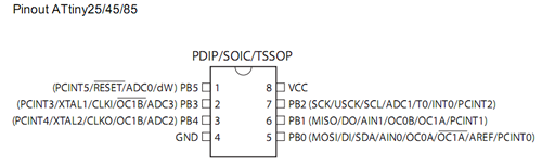
During normal operation there is a bit of variation between successive readings, I'm not sure whether this is just due to thermal fluctuations or an artifact of the ATtiny's ADC.

The starting battery voltage was logged at an unsurprising 1.51v but the last reading received was an astonishing 0.28v! This shows the amazing ability of the step-up voltage converter to suck every last drop of juice out of a battery. Here we have zoomed in on the end of its life:
Each transmission carries a message-ID which should be monotone increasing, within the limits of its range. The next plot shows that the TinySensor worked perfectly (or at least didn't reboot) for most of its run (and also that the message-ID is 16-bits unsigned):

However, towards the end of the battery's life, this is certainly not the case:

Here we zoom in still further on the system's behaviour at the end of the battery's life:
It is clear that the system halts for increasingly long periods of time while the battery recovers, then it manages a few hundred transmissions before collapsing again. We can look at the time interval between messages on the same time axis as the plot above:
Noticing the change in the slope of the message ID line above, let's zoom in on the corresponding part of the inter-arrival time graph:
Note that this is the time at which the message was written to the database on the Raspberry Pi, so some variation must arise from the behaviour of the Linux kernel on that box, however it's not clear what to make of the rising trend in the graph from about 03:37 onwards. (The processor used its Watchdog timer to sleep; this is clocked using its own 128kHz RC-oscillator so perhaps the falling supply voltage is causing time to dilate!)

Update:

A little experiment with an ATtiny, a blinking LED and an almost-exhausted battery disproves the hypothesis that the watchdog timer is losing time: the blink-rate remained constant until the battery died. Furthermore a voltmeter attached to the battery confirmed that it fluctuated up and down by about 10mV during the sketch's blink cycle.

Update 2:

An important lesson from this kind of experimentation is to keep as many sources of time as possible. We've seen the inter-arrival time above, but what about the transmission time as seen by the sensor? Below is a plot of the inter-transmission time, as recorded by the millisecond timer on the ATtiny:
What is really interesting about this is that all of the noise in the inter-arrival times has vanished! As far as the ATtiny is concerned, there are only 4 distinct intervals between packets: 5s (as intended), 10.45s, 15.9s and 21.4s. My best guess for this is that the radio has only succeeded in transmitting one out of every two, three and four packets respectively. Lastly, the steadily rising inter-arrival time is most likely due to radio-level retransmissions, required due to diminishing transmission signal power.

Friday, 7 February 2014

The Next Level

The PCB and TinySensor assembled!
A mere three weeks after submitting the order, Seeed Studio returned my PCBs! The picture above shows one before assembly and the other after. The assembled one is mounted on half of a sick-of-beige case, also from Seeed Studio. This was needed because the PCB chosen was 0.8mm thick and flexes easily. (Perhaps a thicker PCB wouldn't have this problem.)

Assembling a PCB is much easier than stripboard mainly because of the smaller number of holes on offer for each part. Printing the component names helps too but not having them wouldn't have mattered so much, for this project anyway. The main thing to remember is to add the parts in increasing order of height.

The board worked first time! No embarrassing green wires needed! I attribute this to the fantastic job done by Eagle's autorouter. The only change I would make in retrospect is to ensure the capacitors were the right physical size: the parts chosen from Eagle's library had a smaller footprint than the ones eventually used. The Eagle files are here.


Quick-and-dirty graphs of humidity and light from the bathroom over the past 8 hours. (Note the spike at 9am when I was showering!)

Here's the bill-of-materials. Say €20 including headers, nuts-and-bolts, AAA battery, etc.
PartQty
ATtiny84 1 3.00
14-pin DIL 1 0.15
PCB 1 4.50
Sick-of-Beige Case 0.5 1.00
DHT22 1 3.50
NRF24L01+ 1 1.00
NCP1402 3v3 1 5.00
100nF 3 0.05
10k 2 0.05
4k7 1 0.02
Total 18.27

Thursday, 16 January 2014

Taking it to the Next Level

TinySensor Board Layout
Up till now we've just used Eagle to draw schematics and, in all honesty, it's not the world's greatest drawing tool. It only really comes into its own when used as it was intended, to assist the complete design process.

What follows is a summary of my experience using Eagle to lay out the TinySensor circuit, described previously, on a sub-credit-card-sized board and generate the files required to fabricate the board. (It's based on a reading of these two useful posts.)

So, once a circuit has been designed and prototyped on breadboard/stripboard, its schematic drawn and checked for errors (using the ERC tool in Eagle), board layout can begin. Unsurprisingly this involves Eagle's "Switch to Board" menu item. A new window appears with a jumble of interconnected footprints corresponding to the components chosen in the schematic view.

The board view is connected to the schematic so that any changes to the latter are reflected in the former. The first changes might be to replace some components by equivalents with different footprints, for instance (and Eagle provides a tool for just this purpose).

However the main action of this view is layout, routing and manufacture. Layout must be done manually, by dragging individual components out of the jumble and into the white rectangle, representing the board itself. At this stage, I chose the board above (it's from Dangerous Prototypes) and deleted the white rectangle. A good rule of thumb is to place the largest parts first, although you'll probably have a good idea of the desired relative positions of the parts, having prototyped it already on stripboard.

It's good practise to try manually routing the circuit, if only to be even more amazed at what a good job the autorouter does. The undo command is your friend here: I found it useful to try autorouting slightly different placements, undoing autorouting before moving components around.

Once satisfied with the placement, print the layout on paper! This provides an essential sanity check of component footprints: use a pin for the drill holes and attempt to fit your chosen parts. Better to discover they don't fit at this stage than when the boards come back from the fabricator!

The next step is to run a Design Rules' Check. This often requires a rules' file tailored to the fabrication process itself, in this case Seeed Studio's Fusion PCB Service. Download the rules' file, load it from the DRC dialog and run the check. This thread contains descriptions of some errors found at this point.

Finally, run the CAM Processor to generate the design files for manufacturing. (For Seeed Studio, this requires its own Gerber Generator, downloadable from the second step of the Fusion PCB workflow.)
At the CAM Processor dialog, load this file from File > Open > Job... and then hit Process Job. This will generate a bunch of files, of which Seeed requires 8:

% zip seeed.zip sensors.{GTL,GBL,GTS,GBS,GTO,GBO,TXT,GML}

A sanity-check widely recommended at this stage is to load up the layer-files above using a separate tool (e.g., gerbv) to see if there is a discrepancy between it and Eagle and correct it. Once this is done, upload the zip file, pay your money and wait!

Wednesday, 15 January 2014

TinySensor (part 1)

TinySensor circuit diagram
Remote sensing using microcontrollers is nothing new --- it is practically a rite of passage. My spin on it, TinySensor, can be seen above. It's a wireless, battery-powered device which periodically transmits readings of light, temperature, humidity and its own battery voltage, to a base station comprising a Raspberry Pi and a MySQL database. Unusual features of this sensor are:
Resources:

Sunday, 10 November 2013

ATtiny Development Board... now with added Bootloader!

Not long after writing about how ATtinys have no bootloader support, I came across Adafruit's Trinket, an obviously-bootloaded ATtiny85! However as this board's USB bootloader consumes over 2.5kB of flash, it could not coexist with wireless networking in the form of the RF24 library I'm interested in (which leaves only 2.5kB free after inclusion).

Nevertheless, googling "attiny bootloader" turns up several interesting links, notably TinySafeBoot. This is both tiny (550 bytes) and safe (providing password support). Its size means there's still almost 2kB left free in my desired configuration which I expect should be enough for some interesting wireless sensing applications --- stay tuned for more on that.

TSB, which is GPL-licensed, comes with a generic AVR bootloader blob which it tunes for your target hardware, rather than requiring messing with makefiles and building-from-source. In the case of our ATtiny development board, the desired target is an ATtiny84 with pins PB1 and PB0 connected to software-serial Rx/Tx:
% ./tsb tn84 b1b0  # generates tsb_tn84_b1b0_20131023.hex
The resulting bootloader can now be uploaded to the development board using an external programmer. Thereafter TSB talks to the bootloader to upload programs:
% ./tsb /dev/ttyUSB0 FW Blink.cpp.hex
(The bootloader auto-detects the bit-rate which the uploader is using; here I'm just taking the default of 9600B.)

The obvious next step is to integrate TSB into the Arduino IDE, building on the Jeelabs' work to obtain an environment indistinguishable from a normal ATmega-based Arduino; it would simply replace that part of platform.txt, specifying tsb, with appropriate flags, as the uploader.

Unfortunately, I think due to the way tsb handles its input stream, it doesn't take kindly to being called from a script; it's written in freebasic, maybe it's a feature of that platform. So, with the help of strace, I wrote a one-shot firmware uploader in C (gist here) callable from the Arduino IDE.

Now I can upload sketches from the Arduino IDE to my ATtiny development board without any additional hardware! The 'burn bootloader' functionality also works (with the aid of an external programmer) to burn fuses and install the custom firmware file generated above. My fork of Jeelabs' repository is available here, just clone it into your sketchbook/hardware folder.

The only hardware modification I made to my development board was the addition of a series 100nF ceramic capacitor between reset and DTR, to reset the ATtiny when the IDE wants to upload a sketch via FTDI.

Update

A diagram showing the pin names of the ATtiny84 in the Arduino IDE:
Here's a circuit diagram:
The schottky diode acts as a block to allow the board to be powered from an external battery. In this mode, the LED is disabled and no reverse current flows through the regulator. A schottky diode was used because of its low forward voltage drop (0.4v); an ordinary diode would drop the 3.3v supply to 2.6v. (Maybe that's why 3.6v regulators exist!)

Sunday, 3 November 2013

Homebrew msp430 Development Board

While not exclusively devoted to AVR microcontrollers, this blog has concentrated on them for one simple reason: they are very easy to get started with. Whether for beginner (Arduino) or professional (GNU make and gcc), the software ecosystem is very mature. Furthermore, a proliferation of cheap Arduinos (and clones) means that even lack of hardware experience is no barrier to entry.

Texas Instruments has been relatively late to the party with their launchpad line of msp430-based microcontrollers and, until quite recently, a steep learning curve awaited the newcomer. That has all changed with the creation of an Arduino-compatible core for the msp430 and a fork of the Arduino software, Energia, which provides an experience almost indistinguishable from Arduino itself.
msp430 'launchpad' experimenter board

One further thing missing, until now, was ease of prototyping with the microcontrollers themselves outside of the launchpad development kits. The latter actually contain two microcontrollers, one to act as a usb programmer and the other to run user-programs. (While the first actually provides more features than that, that's all a beginner sees.) Thus a hobbyist wanting to use an msp430 for a real-world application had two choices: use the launchpad experimented board itself 'in the field', or program the microcontroller in the experimenter board and then move the newly programmed chip to its permanent home by hand. Easy field upgrades of firmware would require a more complex solution.

Such a solution has been in the works by members of the 43oh community for about a year now. This is a combined USB-stack (cf., v-usb) and bootloader which allows uploading of user programs via a simple USB cable. Only three resistors are required to support USB.

My hardware instantiation of this work (done entirely by others at 43oh and downloadable here) looks like this:
boot430 development board (with g2553)
The bootloader itself is bootstrapped using a development  board: I programmed all of my msp430s at one sitting! Once bootstrapped, user programs can be updated with a simple USB cable and a program called boot430.
Stripboard Layout

The final piece of the puzzle was programming one of these from Energia. Conventionally Energia uses an external program, mspdebug which unfortunately does not speak the same protocol as the USB bootloader. While it is unfortunately not currently possible to configure Energia to use a different uploader, this is a problem which the Arduino team has already encountered and solved in its still-beta version-1.5.

Thus, my somewhat-heretical solution to this problem (at Github): port the Energia launchpad cores back to Arduino, using the same software infrastructure as for the ATtiny development board described earlier. This seems to work quite well, although Arduino has still-unresolved issues in the area of libraries, which leads to confusion about which libraries are actually available on the current platform.

Thursday, 5 September 2013

RF24 with ATtiny84


An ATtiny84 and nrf24l01+ transceiver
The nrf24l01+ is an amazing little wireless transceiver which is (a) incredibly cheap (how about 10 for €8?) (b) can be put into an extremely low-power mode under software when not transmitting and (c) is controlled over SPI (available on Arduino). Furthermore Arduino has support for them via the Mirf library. Unfortunately this library isn't super-easy to use (although I've seen worse).

Luckily for us, someone called Maniacbug has produced an excellent pair of libraries (RF24 and RF24Network) which simplify use of these devices considerably, and in a manner consistent with the Arduino way. The latter library makes building meshed wireless networks very easy indeed. (If you're thinking XBee at a twentieth-the-cost, you're way ahead of me.) An RF24Network article describes the design and implementation of an impressively low-cost, whole-building, wireless sensor network scalable to thousands of sensors.

While reading about this sensor network, a question arose: why was it restricted to ATmegas? Surely an ATtiny would be equally up to the job? It turns out that I wasn't the first to think about this. One source of problems was the ambiguous nature of the SPI interface on ATtiny chips.
ATtiny-x5

Although these chips have pins named after SPI functions (SCK, MISO, MOSI) they are primarily for programming the chip over SPI, not for use in the SPI master role, to control other devices. However USI (for Universal Serial Interface), which can be used to implement SPI, is provided. In principle, therefore, it should be possible to talk to an nrf24l01 radio from an ATtiny, and it turns out by forking the Mirf library, it has been done.

While USI-SPI is demonstrated only for ATtiny85, mutatis mutandis it is pretty easy to make work on an ATtiny84 as well. (Blindly mapping pins by name works pretty well.) A bigger problem is that RF24 relies on the built-in Arduino SPI library, which only works on ATmegas. This library could be a poster-child for the library-dependency problem --- i.e., how to replace an underlying dependency of a library cleanly. In short, with the current Arduino library handling semantics, it's impossible: only one approach works and that's to edit it. (One small consolation is that it's not necessary to edit it in place, the IDE will search ~/sketchbook/libraries before its built-in libraries.)

My cross-platform SPI library is here, (credit is due to Nick Gammon, SPI85 and JeeLib's RF12 driver). It supports ATtiny-x4 and -x5 as well as ATmegas.


ATtiny-x4
The SPI library uses the pins marked DI/DO/USCK in each of the ATtiny pinouts linked here. (Note that DI/DO are not the same as MISO and MOSI!) For the ATtiny84, SS is mapped to PA7 (pin 6), while on the '85 it's mapped to PB3 (pin 2).

Armed with this library, and the ATtiny development environment described yesterday, it was a simple matter to compile the helloworld_tx example from RF24Network. And, while it compiled fine, it failed to link because the resulting binary was too large for the ATtiny84's 8kB code space. An inspection of the library code revealed extensive use of printf_P, which eats up a lot of flash space on an ATtiny. A quick hack with the C preprocessor and the code size was down to 5700 bytes, leaving a couple of kB for user sketches.

When connecting a radio, DO connects to MOSI, DI to MISO and USCK to SCK. CE and CSN can be set to anything reasonable (check cores/tiny/pins_arduino.c for the Arduino pin mappings).

Here are my forked RF24 and RF24Network libraries.