Wednesday 14 December 2011

Homebrew ISP Shield

Mocking up an ISP on a breadboard as described below is handy as a once-off but gets old very quickly. The pictures show a little "shield" for the homebrew Arduino, which costs about a euro for parts and a couple of hours of time.

Although this shield takes a little longer to construct than it does to wire up the breadboard, it also boasts status LEDs, for Heartbeat, Error and Programming, which ArduinoISP can drive but which were always too much trouble to wire up. (The Heartbeat LED is particularly pretty.)

Soldering it together doesn't take too much effort. The main thing to remember is to solder the headers first on a flat surface so that they are quite vertical and protrude the same distance below the board. (This is actually the trickiest part of the job.)

Since they're so cheap, there's no point not to make separate shields for the 8-pin and 14-pin Tiny AVRs. We'll do these as needed.

Friday 11 November 2011

Remote Sensing with XBees, Software

In order to send AT commands to a remote device, a Coordinator must be in API mode while an End Device can be in either API or AT mode. Putting the Coordinator into API mode requires updating its firmware using a USB-Serial converter and a program called X-CTU (downloadable from digi.com). X-CTU requires Windows to run but it works fine in a VirtualBox, once you plumb through the serial device.

When X-CTU can see your device, read the modem parameters and firmware, change the function set to Coordinator API, and write the firmware back to the device. (If the firmware version on the chip does not support the Coordinator API function set, you will have to pick one which does. Unfortunately, as far as I can tell, the only way to do this is by trial and error: it seems that X-CTU will happily write firmware which doesn't run properly on the XBee. Luckily, Digi's technical support is excellent.)

To send an AT command to a remote device, it must be wrapped in a remote-AT command-frame addressed to the end device and transmitted to it via the coordinator. This is tricky! Eventually I found some Perl bindings which did the trick but before that I had some fun crafting the packets by hand, aided by a handy packet-checker. (That site also hosts a useful FAQ.)

The little script below shows how to set up the end device to read its sensors periodically and transmit them to the coordinator. This is attached to the machine on which this script runs, on a USB-Serial port. Received frames are written to the console.

Thursday 3 November 2011

Burning an Arduino Bootloader

Being able to burn an Arduino bootloader to a new ATmega chip is useful for projects originating on Arduino and transferred to a more permanent home on a circuit-board. If their software is to be changed again, it is very handy to be able to reprogram them from the Arduino IDE.

This is primarily based on information found here and here. (The latter is an excellent resource for discovering what the various fuse bits' configuration values mean.)

Wire up the chip as described in In-System-Programming below. Then read the fuses and lock bits (in order to see what actually needs to be changed):

$ avrdude -q -q -p m168 -P/dev/ttyUSB0 -b 19200 -c avrisp -U hfuse:r:-:h -U lfuse:r:-:h -U efuse:r:-:h -U lock:r:-:h
0xdf
0x62
0x1
0x3f

This tells us that the chip has the following fuse-bits set (for more on the meaning of these settings, see here):
  • SPIEN serial programming and data-downloading
  • CKDIV8, SUT0, CKSEL3, CKSEL2, CKSEL0: internal oscillator at 8MHz (and other defaults)
  • The bootloader is already unlocked: 0x3f
If the bootloader is locked, it must first be unlocked:

$ avrdude -p m168 -P/dev/ttyUSB0 -b 19200 -c avrisp -U -e lock:w:0x3f:m

(Note that this also erases the chip -e.)

The main change we're going to make is to configure the chip to use an external oscillator of higher frequency than 8MHz:

$ avrdude -p m168 -P/dev/ttyUSB0 -b 19200 -c avrisp -U lfuse:w:0xff:m -U hfuse:w:0xdd:m

Next, write the bootloader:

$ avrdude -p m168 -P/dev/ttyUSB0 -b 19200 -c avrisp -U flash:w:ADABoot_168.hex

Finally lock the bootloader, to avoid it being accidentally overwritten:

$ avrdude -p m168 -P/dev/ttyUSB0 -b 19200 -c avrisp -U lock:w:0x0f:m

Friday 30 September 2011

Remote Sensing with XBees, Hardware

The schematic below shows a battery-powered wireless remote temperature and humidity sensor. The wireless part is provided by an XBee Pro Series 2, the humidity sensor is an HIH-4030 and the temperature sensor is an LM335a.


The XBee is configured as an 'end-device' and periodically transmits three analog samples to its 'coordinator': humidity on AD0, temperature on AD1 and supply voltage on AD2.

The most important design decision was to run the XBee standalone, without the aid of a microcontroller, which had several consequences for the resulting circuit:
  1. It constrained the choice of humidity sensor to the relatively-expensive Honeywell part, which outputs a voltage proportional to temperature. (Cheaper parts, such as this one, output digital data requiring a microcontroller to present it to the XBee.) 
  2. The Honeywell part demands a 5v supply, and the XBee no more than 3.3v, entailing the further purchase of an Explorer Regulated to step-down the supply voltage for the XBee. (This is not shown in the diagram.)
  3. The analog inputs on the XBee can only read up to 1.2v, so each sensor's output must be passed through a resistive divider to scale it down.
  4. To conserve power, the XBee spends most of its time asleep, waking only to read the sensors. Its ON/SLEEP pin is asserted when it wakes but, of course, doesn't supply the correct voltage for the sensors, so a transistor is needed to switch the 5v supply.
Had the decision to use a microcontroller been taken instead (using an ATtiny85v, say) the entire circuit could have run from 3v, considerably reducing cost and hardware-complexity.

(The diagram was made with Eagle for which Sparkfun provides a library of circuit elements for most of the parts it supplies.)

The software side of this project will be described in a subsequent posting.

Saturday 10 September 2011

Open Source is Wonderful, part 94

A couple of years ago, I bought an ICE Tube clock kit from Adafruit Industries. Not having touched a soldering iron in twenty years meant that I found this quite a tricky build, wiring the tube in particular. (However the online instructions were excellent, and can only have improved since.)


At the time, I'd spotted that at its heart was a programmable chip of some sort but having no idea what an ATMega was: I was happy enough to have built the thing and bask in the reflected admiration of visitors.

Until last night, that is, when I noticed that it was out by five minutes, having only been adjusted six months earlier! Comparing this with my ancient (though also digital) radio alarm-clock whose time is only adjusted after a power-cut, I wondered if I didn't know enough about AVRs now to modify the firmware to implement some sort of drift adjustment.

So I googled "icetube firmware" to find the software it had come with, and discovered there are at least four different firmware versions available, two of which have a drift adjustment feature. I went with jsgf's one, which has a bunch of other cool features, such as day- and night- brightnesses, animated transitions and the ability to turn off the seconds' display altogether (this was a deal-breaker for me originally to use it as an alarm clock).

So I ripped out the chip, discovered it was an ATMega 168v, and threw together a programmer for it, based on the In-System Programming article below --- I've updated the table there with pins for the ATMega series. Total time to implement this feature thanks to OSS? 30 minutes, as determined by the amount I had to update the clock by when I powered it back on!

Friday 12 August 2011

Twilight


The circuit above implements a light switch which is activated by darkness and movement, using an LDR and a PIR sensor respectively. It draws its power from the voltage it's switching, using a 7805 voltage regulator (on the left). A manual override switch is also provided.

The sketch below implements the brains of this circuit. Highlights are:
  • It smooths the light reading using an array of samples to prevent accidental triggering.
  • Hysteresis also helps with this, a light reading below the light threshold is definitely daylight, while one above the dark threshold is definitely night-time.
  • The light level is tunable using a potentiometer, when it's between the light and dark thresholds, an LED is lit indicating dusk.
  • Another LED is lit, using the signal from the PIR, when motion is detected. This is useful when positioning the box in daylight!
  • A manual override is provided to turn on the light for half an hour when it's daytime, and turn it off for 15s at night-time. (The latter allows the light to be turned off and the operator time to get out of the way.)
Several iterations were required to get the switching behaviour just right for the way it was to be used (in a kitchen). Had it been implemented using discrete hardware, it would not have been so easy to make these changes.


Wednesday 13 July 2011

Observations on the ATtiny44

Back here, where I discussed Arduino IDE support for the ATtiny core, I mentioned that I didn't think the -44 was properly supported (although I'd had success with the -84); since then I've confirmed this.

I became sure that the source of the problem was just the various switches passed by the IDE to the native compiler and linker after a day's fiddling with them (you can inspect them by starting the IDE from a shell) and soon afterwards, rather than writing one of my own, I discovered Martin Oldfield's excellent Makefile.

In order to use it, I had to tweak it a bit (you can find my version here), principally to produce, and link against, an Arduino core library; Martin's version links all of the objects into the final image which made it too big for the -44.

One last -44 hint: never use floating-point mathematics: since none of the AT chips has a floating point unit, gcc has to insert software floating-point operations which are not cheap! They add about 1.5kB to the final image, leaving very little space for your precious program!

Sunday 5 June 2011

XBees are Great - Part 1

I wanted to create some remote sensors for a project recently. I needed a Passive Infra-Red (PIR) sensor, an RFID card reader/writer and a gesture sensor based on photo resistors. I wanted them to be wirelessly connected so that I could place the boxes wherever I wanted without having to worry about wiring issues.
I chose to use XBee wireless modules for the communications. They use a protocol called ZigBee designed for low power applications with limited distance communications, rather like Bluetooth but better designed. I had heard favourable reports about XBees and decided to try them out.

The selling features for me were that they:
  • Form themselves into a mesh network without any commands from me.
  • Can send serial data from one radio to another
  • Have up to ten digital I/O ports
  • Have up to four analogue input ports
  • Can periodically send input readings to a controller radio.
  • Input pins can be interrogated remotely
  • Output pins can be set remotely

The radios run off 3.3V but can tolerate 5V on the I/O pins. The analogue input ports measure 0v to 3.3V and produce a number in the range 0-255.

These features mean that the radios can be used stand-alone for many applications (switched, LEDs, voltage measurement) or with an Arduino for more complex applications.

I bought some from eBay. I got Series 2 radios as they have more features than Series 1 and I would recommend getting Series 2 if you buy some; Series 1 and Series 2 radios are not compatible. Obviously you need a minimum of two radios! As you can see in the picture above, XBee radios are small printed circuit boards with a wire or chip antenna on top and two rows of connectors on the bottom.

I also bought at the same time some XBee shields for my Arduinos. These shields look like this:


This was a mistake. I certainly did not need more than the number of Arduinos that I had. Also I discovered that none of the I/O pins on the XBee, once it is plugged in to the shield, are connected to the Arduino, wires have to be soldered in to achieve this. Another thing I did not like about the shield was that some of the Arduino's pins are hidden and become unavailable.

Mistake two was not having a way of connecting a USB cable to an XBee for programming it as a controller or a router. You need one controller in a network, the others, the routers, obtain addresses from the controller.

I found some Sparkfun boards that fitted the bill and bought some of those. The one below connects a USB cable with a standard mini-USB connector to the XBee. This board can be used for reflashing the firmware to con figure the radio or it can be used to connect a desktop or laptop to the radio system to give access to the other radios. The only way to reflash the firmware for reconfiguration or upgrading the firmware is to use a special configuration program (XCTU) on a Windows computer. The site says that it will not work on 64 bit systems but it does, I have had no problem using Windows 7 on a 64 bit system.


The other boards I bought for the XBees were simply breakout boards allowing me to plug the XBee into a breadboard if I wanted to. These boards also have a 5V to 3.3V converter allowing 5V to be used to power everything if desired.


These boards have to have header strips added to them to be able to plug them into a breadboard. I used one board with a four pin header on the end of the board for serial communications and power and ground.

(This article will be continued with some simple use cases)

Wednesday 25 May 2011

One-Wire Mains Switch


The schematic shows a one-wire controlled mains switch. One-wire is a simple protocol which is typically used for networks of temperature sensors. (The diagram is a simplified version of a circuit by Simon Atkins.)

Features of this circuit are:
  • The diodes on the left provide surge protection, for those occasions when your network is hit by lightning.
  • The DS2406 is active-low, the LED is entirely optional.
  • The RC pair at the far right is called a snubber. It is used for inductive loads (e.g., electric motors) when the current is out of phase with the voltage. The resistor should be rated at 1W and the capacitor 400v.
  • The resistor R3 is required to limit the current through the opto-isolator during the instant of time when it is conductive but before the triac has switched on.

Frankenstein's Thermometer, redux

Finally managed to find a diagramming program I didn't dislike: a freeware version of Eagle. It produced the following circuit diagram for the thermometer:

There's not too much to say about that circuit, except that an ATtiny24 probably doesn't have enough storage to run the program. I used an -84. (Note that I don't think that arduino-tiny supports -44 chips yet.)


Here's a picture of the finished "product" in mid-measure:

It runs on two AAA batteries.

Thursday 19 May 2011

It's the little things


One of the first lessons learned by anyone attempting to cook even a moderately complicated meal is do as much preparation as possible. The fewer steps which remain at runtime (as it were) the fewer the opportunities to poison guests.

As with cookery, so with hardware. Frequently-used subsystems, built and tested independently, are an invaluable aid to rapid prototyping. The picture above shows three:
  1. A power cable to carry +5v from the development board to the breadboard,
  2. A breakout board for a magnetic sensor, implementing the manufacturer's suggested circuit,
  3. An LED with 470R resistor in series (why don't manufacturers just sell these?)

Tuesday 10 May 2011

In-System Programming


This post describes how to use an Arduino (or compatible, as described earlier) to program an AVR, specifically the ATtiny84. I used this page as a starting-point, although it talks about programming an ATmega, the principle is the same.

I chose the ATtiny because it is a convenient package for standalone applications (14-pin DIL) yet provides 8k of flash and lots of I/O (up to 12 pins).

The first step is to download 
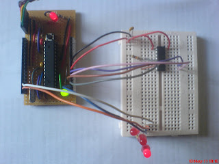
mega-isp into the Arduino IDE and upload it to the Arduino, thus turning it into an ISP. Then wire up the ATtiny as shown in the picture above. The connections between the Arduino and the ATtiny are as follows:


ArduinoATtinyATMegaName
1417Vcc
16148Gnd
13919SCK
12818MISO
11717MOSI
1041/RESET

Also connect the reset pin to Vcc via a 10k resistor and don't forget the 100nF capacitor between Vcc and Gnd.

Status LEDs can optionally be connected as follows:

ArduinoFunction
9Heartbeat
8Error
7Programming

Out of the box, the Arduino IDE supports only ATmega chips. To rectify this, download and install arduino-tiny. Then start the IDE, select Tools > Board > ATtiny @ 1MHz, and compile the sketch to be written to it.

Next, open a shell, find the IDE's working directory (on Linux this is somewhere like /tmp/build8471417854754086173.tmp) and cd into it. Run the following command:
$ avrdude -P /dev/ttyUSB0 -b 19200 -c avrisp -p t84 -U flash:w:Blink.cpp.hex:i
This command writes the output of the compiler (Blink.cpp.hex) at the given baud-rate (19200) to the ISP on the specified port (/dev/ttyUSB0) for the specified part (t84, for an ATMega, m328p). If successful, its output should look something like this:

$ avrdude -P /dev/ttyUSB0 -b 19200 -c avrisp -p t84 -U flash:w:Blink.cpp.hex:i

avrdude: please define PAGEL and BS2 signals in the configuration file for part ATtiny84
avrdude: AVR device initialized and ready to accept instructions

Reading | ################################################## | 100% 0.04s

avrdude: Device signature = 0x1e930c
avrdude: NOTE: FLASH memory has been specified, an erase cycle will be performed
To disable this feature, specify the -D option.
avrdude: erasing chip
avrdude: please define PAGEL and BS2 signals in the configuration file for part ATtiny84
avrdude: reading input file "Blink.cpp.hex"
avrdude: writing flash (752 bytes):

Writing | ################################################## | 100% 1.53s

avrdude: 752 bytes of flash written
avrdude: verifying flash memory against Blink.cpp.hex:
avrdude: load data flash data from input file Blink.cpp.hex:
avrdude: input file Blink.cpp.hex contains 752 bytes
avrdude: reading on-chip flash data:

Reading | ################################################## | 100% 1.35s

avrdude: verifying ...
avrdude: 752 bytes of flash verified

avrdude: safemode: Fuses OK

avrdude done. Thank you.

The ISP's LEDs will blink during this process and the ATtiny will restart when the process has completed, running the newly uploaded sketch.

Note that this does not burn the Arduino bootloader to the chip. Modifications to the sketch require this procedure to be repeated, which is rather laborious.

Thursday 5 May 2011

Frankenstein's Thermometer

Not much more complicated than the simplest thing you can do with an Arduino is measure and display temperature. The picture shows such a device at the embryo stage.

The parts' list for this is:
  • 3x10k
  • 10k NTC thermistor (beta = 3977)
  • 100nF ceramic capacitor
  • 7x470R
  • Pushbutton switch
  • 7-segment LED display (common cathode)
The measurement is performed by a 10k resistor and the thermistor at the top of the picture. This is read by the Arduino on A5 and converted using the thermistor equation.

Each digit of the result is output on digital pins 2-8 in turn. A resistor is required for each segment of the display because otherwise the total current through the display would have to be shared between all of the lit segments; use whichever resistor-decade you have most of.

Finally, digital pin 9 is used to sense the state of the pushbutton. This allows cycling between centigrade, fahrenheit and the absolute temperature scale.

This circuit can be powered by 3v and draws between 15 and 30mA, depending on the digit displayed, indicating that the display is consuming the majority of the power. Thus, a couple of alkaline AAA cells would power this circuit for about 3 days.

If the thermistor is disconnected entirely, it displays -273C, which is nice.

Fritzing is here.


Homebrew Arduino development board

Inspired by Romilly's veroduino but requiring some hand-holding to get me started, I happened upon Oomlout's Component Bundle for Arduino Compatible --- I already had some breadboard lying around. While I was there I picked up a USB-Serial cable (which you need in order to actually program the thing).

Having assembled the kit by following the instructions for the BBAC (hint: you can use plain wire instead of 0-ohm resistors!) and tested that it was working (mostly: the cable is too heavy for the serial port header on the breadboard, it kept pulling it loose, making it next to impossible to download sketches), I decided that the thing would need a permanent home: stripboard (or veroboard as it used to be called).

Here are the bits required for a minimal development board:
  • 6-way male header
  • 2x10k
  • pushbutton (reset)
  • 2x16-way female header (14-way would do but that's all bitsbox had)
  • 16MHz crystal
  • 100nF ceramic
  • 2x22pF ceramic
  • 28-pin DIL socket
  • ATMega328 flashed with Arduino bootloader
  • Stripboard 26 lines x 15 holes
I left off the 5v DC converter circuit because the board gets its power from the host PC, via the serial cable. At your option you may wish to add a power LED, or an additional LED on pin 13, for the 'blink' demo. (The BBAC shows how to wire each of these.)

Once you have this wired up, your breadboard is freed-up for actual experimentation!

The board assembled: