Sunday 10 November 2013

ATtiny Development Board... now with added Bootloader!

Not long after writing about how ATtinys have no bootloader support, I came across Adafruit's Trinket, an obviously-bootloaded ATtiny85! However as this board's USB bootloader consumes over 2.5kB of flash, it could not coexist with wireless networking in the form of the RF24 library I'm interested in (which leaves only 2.5kB free after inclusion).

Nevertheless, googling "attiny bootloader" turns up several interesting links, notably TinySafeBoot. This is both tiny (550 bytes) and safe (providing password support). Its size means there's still almost 2kB left free in my desired configuration which I expect should be enough for some interesting wireless sensing applications --- stay tuned for more on that.

TSB, which is GPL-licensed, comes with a generic AVR bootloader blob which it tunes for your target hardware, rather than requiring messing with makefiles and building-from-source. In the case of our ATtiny development board, the desired target is an ATtiny84 with pins PB1 and PB0 connected to software-serial Rx/Tx:
% ./tsb tn84 b1b0  # generates tsb_tn84_b1b0_20131023.hex
The resulting bootloader can now be uploaded to the development board using an external programmer. Thereafter TSB talks to the bootloader to upload programs:
% ./tsb /dev/ttyUSB0 FW Blink.cpp.hex
(The bootloader auto-detects the bit-rate which the uploader is using; here I'm just taking the default of 9600B.)

The obvious next step is to integrate TSB into the Arduino IDE, building on the Jeelabs' work to obtain an environment indistinguishable from a normal ATmega-based Arduino; it would simply replace that part of platform.txt, specifying tsb, with appropriate flags, as the uploader.

Unfortunately, I think due to the way tsb handles its input stream, it doesn't take kindly to being called from a script; it's written in freebasic, maybe it's a feature of that platform. So, with the help of strace, I wrote a one-shot firmware uploader in C (gist here) callable from the Arduino IDE.

Now I can upload sketches from the Arduino IDE to my ATtiny development board without any additional hardware! The 'burn bootloader' functionality also works (with the aid of an external programmer) to burn fuses and install the custom firmware file generated above. My fork of Jeelabs' repository is available here, just clone it into your sketchbook/hardware folder.

The only hardware modification I made to my development board was the addition of a series 100nF ceramic capacitor between reset and DTR, to reset the ATtiny when the IDE wants to upload a sketch via FTDI.

Update

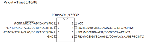
A diagram showing the pin names of the ATtiny84 in the Arduino IDE:
Here's a circuit diagram:
The schottky diode acts as a block to allow the board to be powered from an external battery. In this mode, the LED is disabled and no reverse current flows through the regulator. A schottky diode was used because of its low forward voltage drop (0.4v); an ordinary diode would drop the 3.3v supply to 2.6v. (Maybe that's why 3.6v regulators exist!)

Sunday 3 November 2013

Homebrew msp430 Development Board

While not exclusively devoted to AVR microcontrollers, this blog has concentrated on them for one simple reason: they are very easy to get started with. Whether for beginner (Arduino) or professional (GNU make and gcc), the software ecosystem is very mature. Furthermore, a proliferation of cheap Arduinos (and clones) means that even lack of hardware experience is no barrier to entry.

Texas Instruments has been relatively late to the party with their launchpad line of msp430-based microcontrollers and, until quite recently, a steep learning curve awaited the newcomer. That has all changed with the creation of an Arduino-compatible core for the msp430 and a fork of the Arduino software, Energia, which provides an experience almost indistinguishable from Arduino itself.
msp430 'launchpad' experimenter board

One further thing missing, until now, was ease of prototyping with the microcontrollers themselves outside of the launchpad development kits. The latter actually contain two microcontrollers, one to act as a usb programmer and the other to run user-programs. (While the first actually provides more features than that, that's all a beginner sees.) Thus a hobbyist wanting to use an msp430 for a real-world application had two choices: use the launchpad experimented board itself 'in the field', or program the microcontroller in the experimenter board and then move the newly programmed chip to its permanent home by hand. Easy field upgrades of firmware would require a more complex solution.

Such a solution has been in the works by members of the 43oh community for about a year now. This is a combined USB-stack (cf., v-usb) and bootloader which allows uploading of user programs via a simple USB cable. Only three resistors are required to support USB.

My hardware instantiation of this work (done entirely by others at 43oh and downloadable here) looks like this:
boot430 development board (with g2553)
The bootloader itself is bootstrapped using a development  board: I programmed all of my msp430s at one sitting! Once bootstrapped, user programs can be updated with a simple USB cable and a program called boot430.
Stripboard Layout

The final piece of the puzzle was programming one of these from Energia. Conventionally Energia uses an external program, mspdebug which unfortunately does not speak the same protocol as the USB bootloader. While it is unfortunately not currently possible to configure Energia to use a different uploader, this is a problem which the Arduino team has already encountered and solved in its still-beta version-1.5.

Thus, my somewhat-heretical solution to this problem (at Github): port the Energia launchpad cores back to Arduino, using the same software infrastructure as for the ATtiny development board described earlier. This seems to work quite well, although Arduino has still-unresolved issues in the area of libraries, which leads to confusion about which libraries are actually available on the current platform.

Thursday 5 September 2013

RF24 with ATtiny84


An ATtiny84 and nrf24l01+ transceiver
The nrf24l01+ is an amazing little wireless transceiver which is (a) incredibly cheap (how about 10 for €8?) (b) can be put into an extremely low-power mode under software when not transmitting and (c) is controlled over SPI (available on Arduino). Furthermore Arduino has support for them via the Mirf library. Unfortunately this library isn't super-easy to use (although I've seen worse).

Luckily for us, someone called Maniacbug has produced an excellent pair of libraries (RF24 and RF24Network) which simplify use of these devices considerably, and in a manner consistent with the Arduino way. The latter library makes building meshed wireless networks very easy indeed. (If you're thinking XBee at a twentieth-the-cost, you're way ahead of me.) An RF24Network article describes the design and implementation of an impressively low-cost, whole-building, wireless sensor network scalable to thousands of sensors.

While reading about this sensor network, a question arose: why was it restricted to ATmegas? Surely an ATtiny would be equally up to the job? It turns out that I wasn't the first to think about this. One source of problems was the ambiguous nature of the SPI interface on ATtiny chips.
ATtiny-x5

Although these chips have pins named after SPI functions (SCK, MISO, MOSI) they are primarily for programming the chip over SPI, not for use in the SPI master role, to control other devices. However USI (for Universal Serial Interface), which can be used to implement SPI, is provided. In principle, therefore, it should be possible to talk to an nrf24l01 radio from an ATtiny, and it turns out by forking the Mirf library, it has been done.

While USI-SPI is demonstrated only for ATtiny85, mutatis mutandis it is pretty easy to make work on an ATtiny84 as well. (Blindly mapping pins by name works pretty well.) A bigger problem is that RF24 relies on the built-in Arduino SPI library, which only works on ATmegas. This library could be a poster-child for the library-dependency problem --- i.e., how to replace an underlying dependency of a library cleanly. In short, with the current Arduino library handling semantics, it's impossible: only one approach works and that's to edit it. (One small consolation is that it's not necessary to edit it in place, the IDE will search ~/sketchbook/libraries before its built-in libraries.)

My cross-platform SPI library is here, (credit is due to Nick Gammon, SPI85 and JeeLib's RF12 driver). It supports ATtiny-x4 and -x5 as well as ATmegas.


ATtiny-x4
The SPI library uses the pins marked DI/DO/USCK in each of the ATtiny pinouts linked here. (Note that DI/DO are not the same as MISO and MOSI!) For the ATtiny84, SS is mapped to PA7 (pin 6), while on the '85 it's mapped to PB3 (pin 2).

Armed with this library, and the ATtiny development environment described yesterday, it was a simple matter to compile the helloworld_tx example from RF24Network. And, while it compiled fine, it failed to link because the resulting binary was too large for the ATtiny84's 8kB code space. An inspection of the library code revealed extensive use of printf_P, which eats up a lot of flash space on an ATtiny. A quick hack with the C preprocessor and the code size was down to 5700 bytes, leaving a couple of kB for user sketches.

When connecting a radio, DO connects to MOSI, DI to MISO and USCK to SCK. CE and CSN can be set to anything reasonable (check cores/tiny/pins_arduino.c for the Arduino pin mappings).

Here are my forked RF24 and RF24Network libraries.

Wednesday 4 September 2013

ATtiny84 Development Board

JNµ-alike
 This little board was inspired by a series of articles at JeeLabs describing how to program a JNµ from Arduino-1.5. (I tweaked a couple of values in its boards.txt but otherwise it's as described there.)

Background: since the ATtiny has no bootloader support, it can't be programmed with an FTDI cable but requires an ISP (e.g., an Arduino running the ArduinoISP example) to upload sketches to it over SPI, via avrdude (as seen below). The latest version of the Arduino IDE now supports this from within the IDE itself.
Programming it.
However I chose to add an FTDI connector because the authors of the arduino-tiny core had cunningly added a transmit-only serial emulation (on pin PB0 on the ATtiny84). (While a SoftwareSerial library which can also receive data exists, it's not yet supported on IDE 1.5.2. However I added future support for it anyway by wiring the receive line to PB1.)

Board layout
But wait, there's more! This fine article points out an alternative to ArduinoISP, which can also act as a serial relay: TinyISP. It provides two ways of doing this: by relaying SoftwareSerial and a (more robust) alternative called Knock-Bang. Each of these methods uses the SPI lines so no extra connector is required. This allows programming an ATtiny in almost the same way as an Arduino --- except you need an Arduino to act as a serial port for it!

Monday 29 July 2013

Weather Guy


The picture shows a little Weather Station based around an ATmega328. What makes this one interesting is that it gets its weather data from Yahoo! Weather rather than a bunch of sensors. What's interesting about that (to paraphrase Dr Johnson) is that it can be done at all on an 8-bit microcontroller.

The hardware components of this system are not worth drawing a circuit diagram for:
  • Basic ATmega328 with 16MHz crystal and 22pF balancing capacitors (you know the score)
  • An ENC28J60 ethernet module (e.g., from eBay)
  • An ST7735 TFT display with SD-card (e.g., from Adafruit)
  • Stripboard, connectors, etc.
  • Err, that's it!
The software is where the real action lies. This baby (a 600+ line sketch!) crams in the following libraries:
The restrictions of the AVR chip steered the implementation in interesting directions:
  • All string constants stored in flash, using either F() or PSTR().
  • Using the TFT screen for debugging rather than Serial (saves 128 bytes RAM).
  • Graphics downloaded from Yahoo! in advance, converted into bitmaps and stored on a cheap SD card.
  • Buffer-sharing between the XML parser and reading from the SD-card. (In particular, most SD-card libraries require their own 512-byte buffer for output, see this earlier post.)
  • Reclamation of some flash on the AVR using Optiboot.
  • Displaying wind-direction without using transcendental functions (i.e., sin, cos) used the nice trick of successive rotations. (This is apparently due to the legendary Marvin Minsky, in hakmem 149.)
There is almost no free space left on the chip: just under 200 bytes of RAM (which I guess is needed for the stack) and 512 bytes of flash!

Here's another picture showing forecast data:


Saturday 27 July 2013

Optiboot

The heart of a cheap Arduino clone is an ATmega328 chip. Often sellers of this chip will assume you're going to use it for an Arduino and burn a bootloader onto it before shipping it to you. But what if you get one without a bootloader? What if you want to use a different bootloader, for example Optiboot?

Optiboot is great: it fits inside a single 512-byte sector of flash, freeing up a (sometimes) precious 1.5kB for your programs. It allows downloading at 115200bps, also handy for large sketches. In conjunction with a 100nF capacitor between RTS and RESET, it turns your homebrew clone into an Arduino Uno (from the point-of-view of the IDE anyway).

So (adjusting your avrdude settings accordingly), firstly read the fuse bits:

$ avrdude -q -q -P /dev/ttyUSB0 -b 19200 -c avrisp -p m328p -U hfuse:r:-:h -U efuse:r:-:h -U lfuse:r:-:h
0xda
0x5
0xff

Check this online calculator for the meaning of these bits. In this case, the value of the high bits (0xda) means that 2k is reserved for the bootloader section, we're only going to need 512 bytes:

$ avrdude -q -P /dev/ttyUSB0 -b 19200 -c avrisp -p m328p -U hfuse:w:0xde:m 

Next program the optiboot bootloader (the version shipped with the Arduino IDE is in hardware/arduino/bootloaders/optiboot):

$ avrdude -q -P /dev/ttyUSB0 -b 19200 -c avrisp -p m328p -U flash:w:optiboot_atmega328.hex -U lock:w:0x0f:m

Now when you power up your Arduino clone, you should see a triple-flash on the LED on pin 13 indicating that Optiboot is ready to receive your sketches.

Monday 15 July 2013

Accessing SD Cards from Microcontrollers

This post reviews the available choices for reading or writing FAT-formatted SD cards from Arduino and Energia over SPI. All of the libraries mentioned here support only 8.3 file-names.

Arduino ships with a library called SD, which is a wrapper (by Adafruit) around the more-comprehensive SdFat library (by William Greiman). Features of this library are:
  • FAT16 and FAT32 support on both standard and high-capacity SD cards
  • File: create, read, write, delete and truncate
  • Directory: create, read, write and delete
  • Multiple volume/partition support
The same author also provides a smaller fat16lib with features:
  • FAT16 support on standard SD cards only
  • File: create, read and write
  • Root-directory support only
Another choice for Arduino is tinyFAT (by Henning Karlsen). Its features are:
  • FAT16 on SD cards
  • File: create, read, write, rename, delete (ASCII and Binary I/O)
  • Root-directory support only, only one file open at a time
Energia, on the other hand ships with a C++ wrapper around a lower-level C-library (by ChaN) called FatFs. This is aimed at embedded systems generally and has broadly similar functionality to SdFat but also supports:
  • Multiple underlying storage technologies (e.g., SD, ATA, USB and NAND)
  • File-system creation
  • Permissions and timestamps
Petit FatFs is a subset of FatFs for 8-bit microcontrollers with limited RAM. Its features are:
  • FAT16 and FAT32 support
  • File: open, read, streaming-read, seek
  • Directory: read
  • Single volume and single file
Petit FatFs also allows features which are not required to be conditionally-compiled out (e.g., FAT32 and directory support). It also allows other libraries' low-level SPI functions to be used, to reduce code-size.

Since FatFs and Petit FatFs were originally Arduino libraries, they can be used on both Energia and Arduino. The converse is not true of FatFs.

An important point which is not obvious is the RAM footprint required. With the sole exception of Petit FatFS, all of the libraries mentioned allocate a static 512-byte buffer --- this is the sector-size of an SD card. 

Saturday 8 June 2013

SqueezePlug LCD

Radio 4, where else?
The picture shows an lcd2usb clone attached to a SqueezePlug server running on a Raspberry Pi. It is housed in a perspex box, retrieved from a workplace bin, in which an Apple Magic Mouse was shipped. (Perspex boxes from Apple make great project housings!) The media server communicates with it via lcdproc and a homebrew perl script, made significantly simpler by the fact that both lcdproc and the Logitech Media Server provide command-line interfaces. The two switches allow playback to be paused and stopped, respectively.
Samsung Camera awesomeness!

While its firmware was used unchanged from lcd2usb, the hardware was simplified by removing the programmable contrast control, support for multiple display types and for in-system programming. Another change was necessitated by the fact that the display used (a JHD204A), while claiming to be HD44780-compatible, has its contrast and Vcc pins (2 and 3) swapped.

The circuit was assembled in typical 'backpack' style on a piece of stripboard. A nice feature of this display is that it provides connector pins at the top and bottom, allowing functions to be connected to whichever edge is most convenient. The layout was performed manually with pencil and grid-paper as shown below.

Friday 19 April 2013

Cheap TFT Displays

The photo shows a (very) cheap 2.4" TFT LCD/SD/Touchscreen combo purchased (as always) from China, via eBay and PayPal. (Love those blemishes!) Here is what the manufacturer thinks it can do:

This device is a parallel TFT display, unlike the SPI one discussed previously. Its bus can be either 8 or 16 bits wide. Even in 8-bit mode it uses up a whopping 12 I/O pins.

It is well supported (on Arduino anyway) by Henning Karlsen's excellent UTFT library. In the picture it is running the UTFT_Demo_320x240 (configured as S6D1121_8, should you care). However you should follow his advice and edit memorysaver.h in order to comment out all of the other devices supported by this excellent library. Even so, the sketch comes in at over 25kB (and you have to partially disconnect it before upload if you have a USB-Serial Arduino-alike because two of those I/Os belong to the hardware serial port).

So this device pretty much maxes out an ATMega328. About the only application I can imagine for this combination is some sort of digital picture frame with touch-swiping. Even then it would be a tight squeeze to get the sketch and the further SD and UTouch libraries in under 32kB --- and that's without reckoning on the I/Os needed to drive the two extra devices.

Friday 29 March 2013

Prototyping Shield

The picture shows a nifty little 5v TFT-display and SD-card combo purchased on eBay for about €10. It is almost identical to an Adafruit product costing twice as much and since it uses the same chip (the ST7735R, should you care) it's compatible with Ladyada's library. (In fact, the Adafruit tutorial is also useful: the sole difference is that the cheapie's backlight pin should be connected to ground, rather than +5v.)
However the star of this show is the little rapid-prototyping shield shown above. It's primary purpose is to be a sort of breadboard substitute for those components which are unbreadboardable, e.g., larger TFT displays with two rows of pins, such as this one:
One way to play around with one of these guys is to solder two rows of male headers at either the left or right sides and connect it to a breadboard (or Arduino) via jumpers. However this ties up your breadboard  (or Arduino) for the duration of the experiment, which for the committed hobbyist, can be indefinite. With one of these handy shields, a slightly more permanent home can be made for your device for much less than the cost of a breadboard!

Sunday 10 February 2013

Heroic Failures: Voice of TicBot

A project such as Magic Mouth (spotted at Dangerous Prototypes) is a fine example of the surprising power of the ATMega chip. With the addition of a simple audio amplifier and the impressive Webbotlib, your humble 8-bit microcontroller can turn English text into speech!

My first attempt at a project with a similar setup simply read text from the serial port and converted it into speech. (You can find the amplifier circuit schematic and Webbotlib code at Github here, it differs from Magic Mouth mainly by not depending on an external Arduino to supply the text to be spoken.) Here is a picture of it in all its homebrew glory; the amplifier is the little board piggybacking the Arduino clone, the 8-pin chip in the middle is an LM386.


Around the same time, I came across an article about a piece of software which tweeted tics: TicBot. While more Eliza-with-Tourettes than major AI breakthrough, it can be very funny:
Under the influence of Xmas cheer, an idea was born... Voice of TicBot! It would be a humble Arduino connected to Twitter by Ethernet, speaking TicBot's words of wisdom in a robot voice! How hard could that be?

The first obstacle was Twitter's use of OAuth; while this solves the problem of third-party web-application authentication, it is a pain for a device without a traditional UI. Thankfully the good people at supertweet.net have solved this problem, providing an OAuth proxy for Twitter to which devices authenticate themselves using good ol' Basic Auth.

It was then quite straightforward to write a little sketch which polled api.supertweet.net every 10 minutes for TicBot's timeline (using JeeLabs' handy Ethernet driver) and grubbed through the response for the id and text fields; no space for a fancy JSON parser here!

The next problem was how to combine the two applications? One an Arduino sketch (in C++) and the other a Webbotlib application (in C). Neither the option of porting the Ethernet driver to Webbotlib nor that of porting the relevant parts of Webbotlib to Arduino was particularly appealing. Moreover the combined size of the two applications exceeded the flash memory limit of the ATMega-328!

Fortunately a solution turned up in the shape of an Arduino port of Webbotlib's text-to-speech module, TTS. (This was a lucky piece of googling --- my Romanian is non-existent.) It required some work because my amplifier expected its PWM input to come from pin 3 whereas the TTS module emitted it on pin 10, which was needed for the Ethernet SPI. Adding the required functionality for PWM on pin 3 was achieved with the help of a nice online tutorial. An Arduino library updated for version 1.0 and with this functionality and some more examples (including the sketch for VoTB) can be found here.

With these problems solved, Voice of TicBot was finally operational! Unfortunately it was also a failure: the gnomic nature of TicBot's utterances combined with the low quality of the speech rendition made it necessary to visually consult twitter.com whenever output was heard! Here's an example of its output.

(All of this reminds me of a (possibly apocryphal) story about Stephen Hawking's first speech synthesizer: his students were pressed into service as translators, due, one assumes, to their familiarity both with the subject matter and the machine's vocal stylings.)