 I wanted to create some remote sensors for a project recently. I needed a Passive Infra-Red (PIR) sensor, an RFID card reader/writer and a gesture sensor based on photo resistors. I wanted them to be wirelessly connected so that I could place the boxes wherever I wanted without having to worry about wiring issues.
I chose to use XBee wireless modules for the communications. They use a protocol called ZigBee designed for low power applications with limited distance communications, rather like Bluetooth but better designed. I had heard favourable reports about XBees and decided to try them out.
The selling features for me were that they:
- Form themselves into a mesh network without any commands from me.
- Can send serial data from one radio to another
- Have up to ten digital I/O ports
- Have up to four analogue input ports
- Can periodically send input readings to a controller radio.
- Input pins can be interrogated remotely
- Output pins can be set remotely
The radios run off 3.3V but can tolerate 5V on the I/O pins. The analogue input ports measure 0v to 3.3V and produce a number in the range 0-255.

These features mean that the radios can be used stand-alone for many applications (switched, LEDs, voltage measurement) or with an Arduino for more complex applications.
I bought some from eBay. I got Series 2 radios as they have more features than Series 1 and I would recommend getting Series 2 if you buy some; Series 1 and Series 2 radios are not compatible. Obviously you need a minimum of two radios! As you can see in the picture above, XBee radios are small printed circuit boards with a wire or chip antenna on top and two rows of connectors on the bottom.
I also bought at the same time some XBee shields for my Arduinos. These shields look like this:
This was a mistake. I certainly did not need more than the number of Arduinos that I had. Also I discovered that none of the I/O pins on the XBee, once it is plugged in to the shield, are connected to the Arduino, wires have to be soldered in to achieve this. Another thing I did not like about the shield was that some of the Arduino's pins are hidden and become unavailable.
Mistake two was not having a way of connecting a USB cable to an XBee for programming it as a controller or a router. You need one controller in a network, the others, the routers, obtain addresses from the controller.
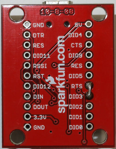
I found some Sparkfun boards that fitted the bill and bought some of those. The one below connects a USB cable with a standard mini-USB connector to the XBee. This board can be used for reflashing the firmware to con figure the radio or it can be used to connect a desktop or laptop to the radio system to give access to the other radios. The only way to reflash the firmware for reconfiguration or upgrading the firmware is to use a special configuration program (XCTU) on a Windows computer. The site says that it will not work on 64 bit systems but it does, I have had no problem using Windows 7 on a 64 bit system.


The other boards I bought for the XBees were simply breakout boards allowing me to plug the XBee into a breadboard if I wanted to. These boards also have a 5V to 3.3V converter allowing 5V to be used to power everything if desired.

(This article will be continued with some simple use cases)