Thursday, 7 December 2023

Desoldering stuff

Progress? Maybe!


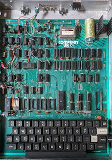
Last time, the next planned step was to remove all of the bodges and restore the machine to something resembling a "factory configuration". This aim has changed slightly: a lot of the bodges are gone but some remain:
  • The 48x32 display mod was just too tricky to undo without a display to test it against.
  • Similarly will leave the 300/600 baud and RS-232 mods until a later time.
  • The monitor switch mod also stays until the EPROM has been verified to work.
So what has been done here?
  • The piggybacked RAM and its decoding logic is history. New sockets were added where necessary.
  • The 6522 VIA board is also gone.
  • A new expansion socket was added to facilitate testing with a Logic Analyzer.
To replace the IC sockets I found the following tools essential:
  • Soldering Iron and solder
  • Desoldering pump
  • Headband Magnifier
  • Bench vise
Don't expect existing IC sockets to survive this process! 
  1. Use the desoldering pump to remove most of the solder; this helps free some of the pins but others will probably remain attached. 
  2. Gently lever the socket away from the board: it will likely break, leaving some pins in place. 
  3. Desolder these one by one. 
  4. Some VIAs will most likely remain at least partially full of solder. To clear them, mount the board vertically in the bench vise and heat each VIA from one side while applying the desoldering pump from the other. It may be necessary to fill the VIA with solder before attempting to clear it, counter-intuitive but it works!
  5. When inserting a new socket do not use force. If it doesn't go in easily, repeat step 4 until it does!
To desolder an unsocketed chip:
  1. Use the pump to remove most of the solder as before.
  2. With a small screwdriver gently push each pin until a click is heard. This means the pin is mostly free of solder.
  3. From the other side of the board, gently lever the chip away from the board. If it doesn't move, mount the board vertically as before, heat the pins on the chip side while applying the desoldering pump from the other. Repeat!
This all requires patience, and a steady hand! 

Flux pen, Desoldering braid and Pump

I also ordered a flux pen and desoldering braid which should be as good or better as the desoldering pump. However I wasn't able to get good results with it. Perhaps my soldering iron isn't hot enough?

Adrian's Digital Basement has a great tutorial on this subject. He also has better tools than I do!

Sunday, 22 October 2023

Restoring a UK101


Yes children, computers looked like this once

This contraption is a Compukit UK101 built over 40 years ago by me from a kit. If I remember right, the kit cost £99 (so must have been one of the last ones) and was smuggled across the UK-Ireland customs border in my parents' car.

Its home is a case made out of aluminium by my brother in our school's metalworking shop. Until fairly recently it resided in my father's attic before being rescued in a clear-out.

An unusual feature (by modern standards anyway) was that its manual contained full schematic diagrams. This led to the proliferation of many third-party hardware modifications, in addition to the ones mentioned in the manual itself. I implemented several of the easier ones.

Under the hood.

Under the hood, it is quite a mess! This was a result of inexperience and lack of funds to "do things right". Looking at the board now, the modifications I seem to have made (or at least attempted) are:
  • Switchable Monitor ROMs
  • Double-speed CPU, to 2MHz
  • Double height display, to 64x32 characters
  • Double-speed tape interface, to 600 baud (or maybe even 1200?)
  • RS-232 interface (used to communicate with a Sinclair QL)
  • 8kB RAM expansion, from 1kB (below the UHF modulator and PSU)
  • Extension ROMs 
  • VIA-6522 board (above the keyboard, on the right)
Some time in the 1990s, I pulled all of the ROMs and read them to use as the basis for an emulator which has been described before here. This explains the empty sockets above the keyboard, on the left.

Whether it still works or not is anyone's guess but inspired by Usagi Electric's fine work on a Centurion mini-computer, I've decided it might be an interesting project. A rough outline of the steps involved might be:
  • Verify the power-supply is working. Done!
  • Remove all of the piggy-backed chips and other bodges; replace IC sockets where required; test RAM chips and leave 1kB system RAM and 1kB display RAM.
  • Using a 16-channel logic analyser and the excellent 6502 decoder project, verify that the system boots by comparing the CPU trace to that from the UK101 emulator.
  • Clean up the video circuitry by connecting to a video monitor, either by buying an old one second-hand, or using this adapter to connect to a modern (HDMI) one.
Once all that has been done, I can start to think about adding new hardware:
  • 32kB static RAM chip (62256-80 seems to be suitable) and 16kB ROM (27C128). The former will occupy the lower half of the address space (0000-7FFFh) and the latter the next quarter (8000-BFFFh).
  • Display modifications: double-height, colour.
  • I/O board: disk controller, VIA
One very interesting possibility would be to build a "universal hardware module" out of an Arduino (e.g., an esp32). This would run a modified UK101 emulator and provide all of the missing hardware by listening on the address bus, data bus and CPU control lines. The CPU would initially have no RAM or ROM: it would all be provided by the emulator. (This idea is reminiscent of the ROMulator as featured on Adrian's Digital Basement but would be more flexible.)

Quite a laundry list there: stay tuned!